KONGSBERG K-Sync
• When new profiles are created, they are appended to the end of the list.
Diagnostic tool
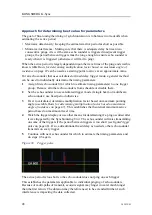
The
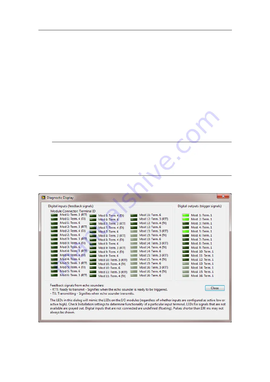
Diagnostic display
shows the signal level on each input and output of the
Synchronizing Unit. There are up to 48 inputs (feedback signals) and up to 16 outputs
(trigger signals) depending upon hardware configuration of SU.
In figure
on page 52, the dialog for the
Diagnostic display
is shown.
The label next to each LED describes which module and terminal number it is associated
with. The module and terminal number refer to the physical connections inside the
Synchronizing Unit.
Note
The LEDs refer to the actual voltage level on the input (referred to as 5 V). If signal
conditioning has been applied, the states may become inverted. For instance, if signal is
set up for RS-232, the LED is on when voltage is -12 V; off when voltage is +12 V. If
set up as TTL, then LED is on for +5 V and off for 0 V.
Figure 42
Diagnostic display
The
Diagnostic Display
dialog shows the signal level of each digital input and output.
52
342435/B


