background image

18

G210–57/3

Operating procedures

Topics

Setting up the radio site for operation, page 18

Joining a wireless network, page 22

Editing an existing radio network, page 23

Adding or removing equipment, page 25

Enabling the embedded MBR link crypto, page 26

Checking the status of the MBR network, page 27

Setting up the radio site for operation

The setup is done using a wizard. The

MBR Configuration Wizard

. A

radio site

is one

or several radio units connected together by a local Ethernet connection at the same
location. A

radio network

is a wireless network of radio sites. You must set up the radio

site before you can start the radio network configuration. All configuration of the MBR
144 Personal Maritime Broadband Radio (MBR) is done through the web interface.

Prerequisites

The IP address for the Radio Unit is located on a label at the rear of the unit. You must
have enabled contact with the Radio Unit.

The IP address and the MAC address for the third party equipment must be known.

Context

The MBR 144 Personal Maritime Broadband Radio (MBR) uses static layer 2 bridging
(OSI model - Open Systems Interconnection Basic Reference Model). It needs both the
IP address and the MAC address of the equipment in order to establish an IP connection
over the wireless network.

MBR 144 Personal Instruction Manual

Summary of Contents for MBR 144

Page 1: ...Instruction Manual MBR 144 Personal Maritime Broadband Radio ...

Page 2: ......

Page 3: ...G210 57 3 March 2022 Kongsberg Seatex AS MBR 144 Personal Maritime Broadband Radio Instruction Manual ...

Page 4: ...Improper use or maintenance may cause damage to the equipment and or injury to personnel You must be familiar with the contents of the appropriate manuals before attempting to operate or work on the equipment Kongsberg Seatex disclaims any responsibility for damage or injury caused by improper installation use or maintenance of the equipment Disclaimer Kongsberg Seatex AS endeavours to ensure that...

Page 5: ...ng contact with the Radio Unit 15 Defining the IP address on the computer s network adapter 16 Operating procedures 18 Setting up the radio site for operation 18 Joining a wireless network 22 Editing an existing radio network 23 Adding or removing equipment 25 Enabling the embedded MBR link crypto 26 Checking the status of the MBR network 27 User preference procedures 28 Selecting colour palette f...

Page 6: ...ng helmet brackets 52 Cable layout and interconnections 53 Setting to work summary 54 DRAWINGS 55 About drawings 55 Radio Unit dimensions fixed mount 56 Radio Unit dimensions helmet mount 57 TECHNICAL SPECIFICATIONS 58 Performance specifications 58 Interface specifications 58 Frequency specifications 59 Weights and outline dimensions 59 Power specifications 60 Environmental specifications 60 Stand...

Page 7: ...G210 57 3 5 Unpacking and handling 65 Storage 66 Disposal 66 Instruction Manual ...

Page 8: ...6 G210 57 3 MBR 144 Personal ...

Page 9: ...rs License information The MBR 144 Personal is not subject to product licensing The product is a radio transmitting device A frequency license is required for operation Maintenance purposes This manual is also intended as reference material for the maintenance personnel Keep this manual for later use Software version The Operation chapter in this document is for Maritime Broadband Radios with soft...

Page 10: ...phased array digital radio units The MBR 144 Personal is intended for operations where personnel require a robust communication link during surveillance and inspection The tilted antennas are suitable for helmet mounting The MBR 144 Personal is also available with a dedicated plug and play camera for live streaming and battery packs The MBR 144 Personal is an Ethernet based radio that requires no ...

Page 11: ...e benefits of a radio site with several radio units is an increased coverage area or redundancy with radios covering the same area Data links to remote MBR units will seamlessly be handed over from one Radio Unit to another Radio Unit on the same radio site All antennas radio transceivers and signal processing are contained in the radio unit The MBR 144 Personal is set up via a web interface which...

Page 12: ...repair of this product only under the given terms and conditions stated in the sales documents Consequential damages such as customer s loss of profit or damage to other systems traceable back to this product s malfunctions are excluded The warranty does not cover malfunctions of the product resulting from the following conditions Incorrect power connection Radio frequency license This product con...

Page 13: ...a Class A digital device pursuant to Part 15 of the FCC Rules These limits are designed to provide reasonable protection against harmful interference when the equipment is operated in a marine and or commercial environment This equipment generates uses and can radiate radio frequency energy If not installed and used in accordance with the instructions the equipment may cause harmful interference t...

Page 14: ...e co located or operating in conjunction with any other antenna or transmitter This product contains a radio transmitting device According to the output power of the equipment the minimum distance for human beings in a controlled environment is Maximum power ETSI EN 303 276 40 cm FCC part 15 407 20 cm Health and safety Operation or troubleshooting of this equipment will not imply any risk for high...

Page 15: ...re or unintentional access by external users Securing the MBR 144 Personal system itself has no meaning unless there is a policy in place that secures all computers in the network This policy must include physical access by trained and trusted users The customer end user of the MBR 144 Personal system will always be in charge of defining and implementing a security policy and providing the relevan...

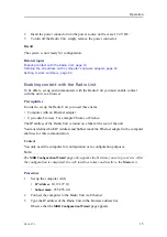
Page 16: ...Unit page 15 Defining the IP address on the computer s network adapter page 16 Turning on the Radio Unit The Radio Unit is turned on when the power connector is inserted in the power source on the vessel The system power is controlled from the power source Context The software is pre installed and the system will start automatically after it has been turned on Procedure 1 Make sure that the Ethern...

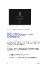
Page 17: ...hernet adapter Up to date browser For example Chrome or Firefox The IP address of the Radio Unit is found on a label at the rear of the unit You must define which IP Address and Subnet mask the Ethernet adapter in the computer shall use for this communication Context You only need the computer for configuration or re configuration purposes Note The MBR Configuration Wizard page only appears the fi...

Page 18: ...mask the Ethernet adapter in the computer shall use for this communication As long as you do not replace the computer or the network adapter you only need to do this once Prerequisites This procedure is made for the Microsoft Windows 7 and 10 operating systems It is assumed that you are familiar with the Windows operating systems computer technology and interface principles Procedure 1 Close all t...

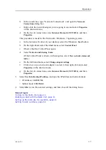
Page 19: ...work and Sharing Center If the Control Panel is shown with categories select View network status and tasks e On the left hand menu select Change adapter settings f Click once on your network adapter to select it then right click and select Properties on the shortcut menu g On the list of connections select Internet Protocol 4 TCP IPv4 and then Properties 3 Select Use the following IP address and t...

Page 20: ...work of radio sites You must set up the radio site before you can start the radio network configuration All configuration of the MBR 144 Personal Maritime Broadband Radio MBR is done through the web interface Prerequisites The IP address for the Radio Unit is located on a label at the rear of the unit You must have enabled contact with the Radio Unit The IP address and the MAC address for the thir...

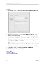
Page 21: ...onfigure site to start the installation wizard Note The default colour palette setting is with dark background If your current light conditions require white background select the white colour palette in the Palette group 2 Select Start on the Configuration guide page to start the step by step configuration of your radio site Operation ...

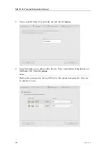
Page 22: ...t Continue 4 Select the radios you want to add to the site Type a description of the location of the Radio Unit Select Continue Note Radio units connected on the local Ethernet will appear automatically They are by default selected MBR 144 Personal Instruction Manual ...

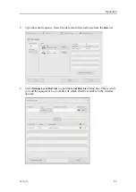
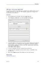
Page 23: ...elect the data rate for the radio site from the Rate list 6 Select Manage Local Host List to open the Local Host List dialog box This is where you add the equipment to your radio site which shall be available in the wireless network Operation ...

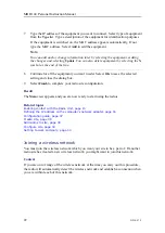
Page 24: ...sh to complete your radio site configuration Result The Main view appears and you are now ready to start using the radios Related topics Enabling contact with the Radio Unit page 15 Defining the IP address on the computer s network adapter page 16 Configuration guide page 37 Create site page 38 Add radios to site page 39 Configure site page 40 Setting to work summary page 54 Joining a wireless net...

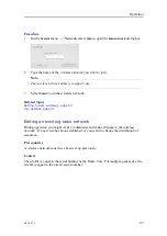
Page 25: ... to work summary page 54 Join network page 47 Editing an existing radio network During operation you might want to administer and make changes to the wireless network If a new site has been established or you want to change the distribution of resources Prerequisites A wireless network must have been set up previously Context The site ID is equal to the serial number of the Radio Unit For multiple...

Page 26: ...enter the Resource management dialog box If you want to adjust the superframe type the wanted Superframe length Type the wanted Resource distributionin the Site list Note For Superframe length it is recommended to use 50 100 ms However for special applications the superframe can be adjusted This will affect the data throughput 4 Select OK to store the bandwidth settings and return to Edit network ...

Page 27: ...x 3 Type the IP address of the equipment you want to connect Select type of equipment from the Type list Type a description of the equipment for identification purposes If the third party equipment is switched on the MAC address appears automatically If not type the MAC address Select Add to add the equipment 4 To remove equipment select the X symbol at the end of the line 5 Continue for all the e...

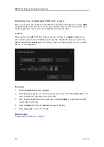
Page 28: ...cifies whether the key is stored in the MBR configuration indefinitely or if the key is lost on the next power cycle or until the key is re configured Procedure 1 On the System menu select Crypto 2 Select Generate key if you want to generate a new key Select Load from file if you want to upload a crypto key from a text file 3 Set a specific duration for the crypto key or select Infinite if you do ...

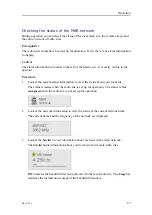
Page 29: ...tion to view the status about your local site The status is Active when the radio site is set up for operation The status is Not configured when the radio site is not set up for operation 2 Look at the network information to view the status of the current radio network The current name and the frequency of the network are displayed 3 Look at the Site list to view information about each site in the...

Page 30: ...on page 29 User preference procedures Topics Selecting colour palette for display page 28 Selecting colour palette for display You can select a colour scheme for the display which suits your current light conditions Context The Palette function provides colour schemes for the display presentation Two palettes are available Day black and Day white Procedure 1 Select Palette on the System menu 2 Sel...

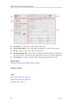
Page 31: ...ystem menu Related topics Menu system page 36 Display organisation The display is made up of five main parts Information boxes with information about the status of the overall system the networks and the radio sites to the left A System menu from which you operate and configure the system at the top Below the System menu various views will appear depending on which of the information boxes to the ...

Page 32: ...tion views Three views may appear here depending on which box is selected to the left System Overview Network Overview or Local Site information E System menu It provides various system settings and operational functions Related topics Checking the status of the MBR network page 27 Display views Topics System Overview view page 31 Network Overview view page 32 Local Site view page 33 MBR 144 Perso...

Page 33: ...tes with more than one Radio Unit panel Select this option to show more information about the other Radio Units which belong to this multipanel site Site name This is the name of the remote radio sites in the network Serial number This is the serial number of the radios on each individual remote site Signal margin dB This is the receiver signal margin for the remote radio site s Distance m This is...

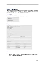
Page 34: ...twork Host List The Network Host List is the combination of all the Local Host Lists in the wireless network How to open Select the Network status box to the left in the Main view Example Details Network ID This is the hexadecimal value of the network name used for identifying that each radio is on the same logical network MBR 144 Personal Instruction Manual ...

Page 35: ...illiseconds Contention period is also called Open period and is a contention based multiple access protocol which allows radio sites to communicate without having a fixed allocated time slot Site name This is the name of the radio sites in the wireless network Contention free slot ms This is the reserved transmission time for a radio site IP This is the IP internet protocol address of the equipmen...

Page 36: ...ink crypto functionality Relay This shows the status of the relay functionality for this site if the relay functionality has been enabled Transmit utilisation This is the current transmission utilisation percentage of the allocated resource contention free slot Transmit kbps This is the current transmission in kbps Sent IP frames This is the number of sent IP frames from this site MBR 144 Personal...

Page 37: ...ows the frames which have not been sent due to a busy MAC media access control controller Received headers This is the counter for received wireless headers Received datagrams This is the counter for received decoded datagrams Checksum errors This is the counter for Checksum errors Functions and dialog boxes Topics Menu system page 36 MBR Configuration Wizard page 37 Configuration guide page 37 Cr...

Page 38: ...uency the data rate the third party equipment for the local radio site You can also see the radio details for the radios on the local site Advanced Advanced contains a web page with a set of advanced functions tuning and diagnostics These settings are for experienced users only They are not intended for use under normal conditions Therefore they are not described in this document Crypto Crypto ope...

Page 39: ... via the web interface Details Configure site Select the Configure site button to open the installation wizard The wizard takes you through the step to step configuration of your radio site Related topics Enabling contact with the Radio Unit page 15 Configuration guide An installation wizard takes you through the setup of the radio site The Configuration guide page is the first page in the step to...

Page 40: ...p configuration of your radio site Related topics Setting up the radio site for operation page 18 Create site Here you can type the name of your radio site How to open This page is step 2 in the step to step configuration of your radio site MBR 144 Personal Instruction Manual ...

Page 41: ...ame will be displayed in the Site list and in the Network view Related topics Setting up the radio site for operation page 18 Add radios to site Here you can add radios to your radio site How to open This page is step 3 in the step to step configuration of your radio site Operation ...

Page 42: ...Unit Name description Here you can type a description of the location of the Radio Unit Related topics Setting up the radio site for operation page 18 Status page 43 Configure site Here you can set the frequency the data rate and select third party equipment for the local radio site You can also see the radio details for the radios on the local radio site This is also where you make changes to the...

Page 43: ... dialog box shows the serial number product version configured values and diagnostics for the Radio Unit Local Host IP The Local Host List shows the current host name s and associated IP addresses in the Local Host List Manage Local Host List This button opens the Local Host List dialog box Here you can manage equipment which is connected to the radio site Related topics Setting up the radio site ...

Page 44: ...to add to your radio site Type This is a drop down list of various metadata information about the equipment which can be useful to add to your radio site For example computers and motion sensors Description Here you can type a name which describes the equipment you want to add to your radio site When you type in this box the Add button becomes active MAC address This is the MAC media access contro...

Page 45: ... page 40 Status The radio Status box shows the serial number product version configured values and diagnostics for the Radio Unit How to open This box is opened by selecting the Details button in the Add radio to site page or the Configure site page in the step to step configuration Details Description This is the description of the location of the current Radio Unit Serial This is the serial numb...

Page 46: ... number of active antenna elements Related topics Add radios to site page 39 Configure site page 40 Checking the product version page 63 Edit network Edit network allows you to edit the wireless network How to open This dialog box is opened from the System menu Details Network This is the name of the current wireless network MBR 144 Personal Instruction Manual ...

Page 47: ...ibution They show all sites in the current network with the same network name and the resource distribution between the radio sites Resource management This button opens the Resource management dialog box This is where you can change the resource distribution between the radio sites Related topics Editing an existing radio network page 23 Resource management page 45 Resource management Resource ma...

Page 48: ...to communicate without having a fixed allocated time slot Site list and resource distribution They show all sites in the current network with the same network name and the resource distribution between the radio sites Rate This is the operating data rate of the radio site Bandwidth It shows the bandwidth of the radio site for the selected resource distribution and the data rate Related topics Edit...

Page 49: ...the wireless network you want to join The wireless network name is in upper case Related topics Joining a wireless network page 22 Crypto key configuration The MBR link crypto encrypts the wireless link with the use of 56 bit symmetrical keys The same crypto key must be entered on all radios in the same wireless network so the radios can communicate with each other How to open Select the Crypto bu...

Page 50: ...ycle Related topics Enabling the embedded MBR link crypto page 26 System status The System status shows the status for the local radio site The status is Active when the radio site is configured The status is Not configured when the radio site is not configured The System status is located to the left in the Main view The padlock symbol indicates that a crypto key has been enabled Related topics C...

Page 51: ... the local radio site is displayed BW indicates the bandwidth resource allocated to the local site The Usage bar indicates the usage of the bandwidth resource Remote radio site The site name for the remote radio site s is displayed BW indicates the bandwidth resource allocated to the remote site The signal strength bar indicates the signal strength of each local site Related topics Checking the st...

Page 52: ... Radio Unit power requirements page 51 Mechanical drawings Outline dimension drawings are included in this manual Unless otherwise specified all measurements are in millimetres The drawings are not to scale Necessary tools and equipment We assume that you are equipped with a standard set of tools This tool set must comprise the normal tools for electronic and electromechanical tasks This includes ...

Page 53: ...Unit must be powered by a dedicated power supply Mounting the Radio Unit to a fixed structure The Radio Unit is designed with four mounting brackets which must be used when mounting the unit Prerequisites A mounting arrangement for the Radio Unit must be prepared before mounting Context The Radio Unit must be mounted in a 45 degree angle for the four antennas to be aligned vertically This is to ma...

Page 54: ...adio Unit dimensions fixed mount page 56 Mounting the Radio Unit using helmet brackets The Radio Unit can be supplied with bracket for mounting the Radio Unit to a helmet or similar rounded structure Context The Radio Unit is connected to external equipment with the Ethernet end of the combined Ethernet and power cable This cable is attached to the Radio Unit by a connector A Radio Unit mounting b...

Page 55: ...topics Radio Unit dimensions helmet mount page 57 Cable layout and interconnections The cable connections for the Radio Unit consists of Combined Ethernet and power cable from the Radio Unit to user equipment The cable connector type is ODU AMC standard version A10YAR P09XCD0 0000 Radio Unit Ethernet and power connector Pin no Description Cable colours 1 ETH Green 2 ETH Orange White 3 DC 4 DC 5 ET...

Page 56: ...can be turned on and set to work Procedure 1 Turn on the Radio Unit 2 Enable contact with the Radio Unit 3 Configure the radio site 4 Join a radio network Related topics Turning on the Radio Unit page 14 Enabling contact with the Radio Unit page 15 Defining the IP address on the computer s network adapter page 16 Setting up the radio site for operation page 18 Joining a wireless network page 22 MB...

Page 57: ... Unit dimensions fixed mount page 56 Radio Unit dimensions helmet mount page 57 About drawings These drawings are for information and planning purposes only Unless otherwise specified all measurements are in millimetres The drawings are not to scale Drawings ...

Page 58: ...56 G210 57 3 Radio Unit dimensions fixed mount MBR 144 Personal Instruction Manual ...

Page 59: ...G210 57 3 57 Radio Unit dimensions helmet mount Drawings ...

Page 60: ...mity declaration page 62 Performance specifications These performance specifications summarize the main functional and operational characteristics of the MBR 144 Personal Operating range 20 km Dependent on antenna placement and height User data 0 7 16 5 Mbps Available rates 0 7 1 4 2 8 8 5 16 5 Mbps Antenna coverage 360 degrees azimuth omnidirectional Interface specifications The system will inter...

Page 61: ...07 5725 5850 MHz Channel bandwidth 20 MHz TX power HW Maximum Up to 2 W ETSI EN 303 276 Up to 2 W FCC part 15 407 Up to 1 W Maximum EIRP HW Maximum 40 dBm ETSI EN 303 276 40 dBm FCC part 15 407 36 dBm Modulation GMSK Antenna gain 7 dBi Antenna elements 4 Related topics Radio frequency license page 10 Weights and outline dimensions These weights and outline dimension characteristics summarize the p...

Page 62: ...4 Personal Enclosure material Coated aluminium Operating temperature 40 C 40 C Air convection required Operating humidity 20 100 RH Storage humidity 20 70 RH Ingress protection IP code Radio Unit IP66 Ingress protection IP code Connectors IP68 Unmated and mated Standards and regulations This product is in compliance with relevant directives and product standards Radio Equipment Directive RED 2014 ...

Page 63: ...G210 57 3 61 Environmental standards IEC 60945 EN 60945 Radiation hazard standards EN 50385 Technical specifications ...

Page 64: ...62 G210 57 3 Manufacturer s conformity declaration This product is in compliance with relevant directives and product standards MBR 144 Personal Instruction Manual ...

Page 65: ...site page 2 Under Radios select the Details button for the radio for which you want to see the product version Observe that the radio Status box appears Here you can see both the serial number and the product version of the Radio Unit 3 Close the dialog box by selecting X in the upper right corner Related topics Status page 43 Updating the system software We recommend that you keep your product up...

Page 66: ...t software Related topics Support information page 13 Repairing the Radio Unit The Radio Unit is not designed for repair in the field All repairs and modifications of the unit except for installation of new software versions and system setup must be done by qualified personnel A failed Radio Unit should be shipped back to Kongsberg Seatex AS or other agreed service point for repair Related topics ...

Page 67: ...any damage both the insurance company and the shipping agent must be informed immediately Unpacking and handling Care should be taken when unpacking and handling the equipment A visual inspection should be made to check that the equipment has not been damaged during shipment and that all components and parts are present according to the packing list The equipment contains delicate electronic compo...

Page 68: ...posal and separate collection of your old appliance will help prevent potential negative consequences for the environment and human health This is a precondition for reuse and recycling of used electrical and electronic equipment For more detailed information about disposal of your old appliance please contact your local authorities or waste disposal service All disposal of mechanical electromecha...

Page 69: ...og box 49 Local Site view 33 Network Overview view 31 Network status dialog box 48 radio Status box 43 Remote radio site status dialog box 49 Resource management dialog box 45 system 8 System menu 36 System Overview view 32 System status dialog box 48 diagram system 9 dialog box Add radios to site dialog box description 39 Configuration guide dialog box description 37 Configure site dialog box des...

Page 70: ...1 52 interference radio frequency 11 internet network security 12 IP address network adapter 16 IP Address network adapter 16 J join network how to 22 Join network dialog box description 47 K Kongsberg Seatex AS support 13 L license product license 7 radio frequency 10 Local Host List dialog box description 42 Local radio site status dialog box description 49 Local Site view description 33 M main ...

Page 71: ...installing 51 52 power specifications 60 turning on 14 regulations product regulations 60 Remote radio site status dialog box description 49 removing equipment 25 repairing Radio Unit 64 required items not provided with the delivery 10 requirements power 51 Resource management dialog box description 45 restrictions guarantee 10 S safety product safety 12 scope of supply basic items 10 required ite...

Page 72: ...ce 58 this publication about 7 purpose 7 target audience 7 this user manual about 7 purpose 7 target audience 7 tools installation of system units 50 turning on Radio Unit 14 U unpacking equipment 65 upgrading software 63 V version finding product version 63 software 7 view Local Site 33 Network Overview 31 System Overview 32 W waste handling 66 WEEE Waste Electrical and Electronic Equipment 66 MB...

Page 73: ......

Page 74: ... 2022 Kongsberg Seatex ...

Reviews: