G210–57/3
51
tool must be provided in various sizes. We recommend that all tools are demagnetized to
protect your equipment.
Unless otherwise stated, all mounting hardware (such as bolts, nuts, washers, screws
etc.) referred to in this document is to be supplied by the customer or the shipyard.
An external computer is required for configuration of the Radio Unit through a web
interface. You also need a computer if you want to change the configuration later.
Radio Unit power requirements
The Radio Unit must be powered by a dedicated power supply.
Mounting the Radio Unit to a fixed structure
The Radio Unit is designed with four mounting brackets which must be used when
mounting the unit.
Prerequisites
A mounting arrangement for the Radio Unit must be prepared before mounting.
Context
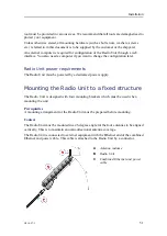
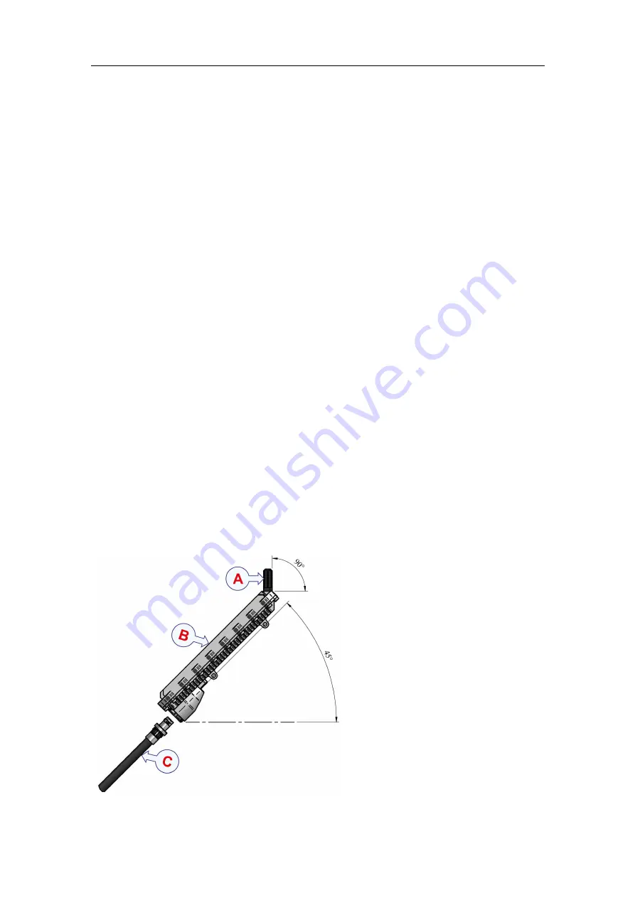
The Radio Unit must be mounted in a 45-degree angle for the four antennas to be aligned
vertically. This is to maintain an omni-directional antenna coverage.
The Radio Unit is connected to external equipment with the Ethernet end of the combined
Ethernet and power cable. This cable is attached to the Radio Unit by a connector.
A
Antenna radome
B
Radio Unit
C
Combined Ethernet and power
cable
Summary of Contents for MBR 144
Page 1: ...Instruction Manual MBR 144 Personal Maritime Broadband Radio ...
Page 2: ......
Page 7: ...G210 57 3 5 Unpacking and handling 65 Storage 66 Disposal 66 Instruction Manual ...
Page 8: ...6 G210 57 3 MBR 144 Personal ...
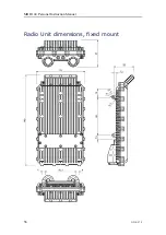
Page 58: ...56 G210 57 3 Radio Unit dimensions fixed mount MBR 144 Personal Instruction Manual ...
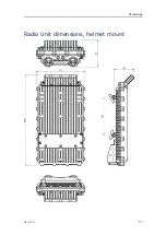
Page 59: ...G210 57 3 57 Radio Unit dimensions helmet mount Drawings ...
Page 73: ......
Page 74: ... 2022 Kongsberg Seatex ...

