background image

JBA Explorer.lnk


OE14-122/23


Underwater Colour Pan, Tilt and Zoom Camera


colour


U

ser


Ma

nua

l


Manufacturing:

  Airport Industrial Estate, Wick, Caithness, Scotland 

tel:

 +44 (0)1955 603606     

fax:

 +44 (0)1955 607520


Sales and Service:

 Campus 1, Science and Technology Park, Aberdeen, Scotland 

tel:

 +44 (0)1224 226500 (24 hrs)     

fax:

 +44 (0)1224 226501


Kongsberg Maritime Ltd 

User Manual: 

OE14-122 Colour Pan, Tilt  and Zoom Camera  - 5023 –5


Page 13 of 14

         14-122-6012 Protection Circuitry Parts list

PCB Ref 

Description 

KML Part number 

C1, C2 

CAP 3-TERMINAL 4700PF 

014-0179 

C3 

CAP TANT   10U 10%  

019-9504         

C4, C10, C22, C23 

CAP CER 100NF 0805 SM 

019-0530         

C5, C6, C7, C12, C13, 
C14 

CAP TANT 150U10% SM 16V 

019-0532         

C8, C15 

CAP 3-TERMNINAL 470PF 

014-0185 

C9 

CAP TANT   22U 10% 

019-9505 

C11 

CAP CER 10U 10V 1206 SM 

019-9551 

C16, C17, C18, C19, 
C20, C21, C24, C25, 
C26, C27, C30, C33, 
C35 

CAP 3-TERMINAL 2200PF 

014-0181 

D1 

DIODE SCHOTTKY 3A 40V  

046-0501         

D2 

DIODE SOD106A 30V SM  

046-0504         

D3 

DIODE BYD17D 1.5A 200V  

046-0500         

D4, D8, D9 

DIODE BYD17D 1.5A 200V  

046-0500        

D5, D10 

SUPPRESSOR TRANS SMBJ30  047-0014        

D6, D11 

SUPPRESSOR TRANS SMBJ15  047-0015        

D7, D12 

DIODE ZENER 16V 1W ZMY1 

047-0506         

D13, D14, D18, D19 

SUPPRESSOR TRANS SMBJ30  047-0008         

D15, D16 

SUPPRESSOR TRANS SMBJ12  047-0505         

R1, R2 

RES 0R0 0805 SM 1% 0.1W 

028-0010         

R3 

RES MET FILM 6R8 1% SM  

028-0312         

R4 

RES MET FILM 5R6 1% SM  

028-9282         

R5, R9, R14, R17 

RES 1K 1W SM MMB0207  

028-0327         

R12, R13 

RES 100R 0805 SM 1% 0.1 

028-0148         

FS1 

FUSE 2A RESETABLE SM  

151-0007         

FS2, FS3, FS4, FS5, 
FS6, FS7, FS8, FS10 

FUSE RESETTABLE 0.1A SM 

143-0045         

FS9 

FUSE 0-5A SM RESETABLE  

143-0030         

TC1, TC2 

TRIAC BT134W-600D 600V  

045-0014         


         Figure 1.2 

Summary of Contents for OE14-122

Page 1: ...S232 RS485 Control 9 Hardwire Control 11 Network Control 12 Circuit Descriptions 13 Protection Circuitry Parts List 14 Fault Finding Sales and Service Campus 1 Science and Technology Park Aberdeen Scotland tel 44 0 1224 226500 24 hrs fax 44 0 1224 226501 Manufacturing Airport Industrial Estate Wick Caithness Scotland tel 44 0 1955 603606 fax 44 0 1955 607520 User Manual Contents OE14 122 23 ...

Page 2: ...reasonable service and what constitutes a reasonable period of time shall be determined solely by the Company after the Company is in possession of all the facts concerning operating conditions and other pertinent factors and after such component or accessory has been returned to the Company transportation pre paid b The Company takes no warranty concerning components or accessories not manufactur...

Page 3: ...bligation to incorporate new features in instruments previously sold Damage in Shipment The Company s instrument is carefully examined and checked before it is shipped It should be visually and operationally checked as soon as it is received If it is damaged in any way a claim should be filed with the carrier New or repaired instruments damaged in transit should not be returned to the manufacturer...

Page 4: ... your reference The items listed on the encapsulation card are classified by Kongsberg Maritime as first level maintenance items and as such can be maintained by the operator Care must be taken however to ensure that the O Rings are lubricated with silicon grease and that no solvents Alcohol etc are used to clean the Correction Lens Your new camera should give many years of quality service However...

Page 5: ...I icon The GUI will then install Follow the on screen instructions while installing the GUI Then plug in a suitable cable into the external connector on the camera and wire it up using the wiring information supplied on the encapsulation card Connect 16 24V d c onto the power pin and connect the 0V pin to ground Connect the video output and screen pins to a VBS connector on a monitor and or a vide...

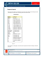
Page 6: ... and to change the LLD setting to provide compensation for losses in cables The following table shows the IR functions IR Functions Button Function RESET No LLD 200 200m 665 ft LLD 400 400m 1330 ft LLD 750 750m 2500 ft LLD 800 800m 2660 ft LLD 1000 1000m 3325 ft LLD 1100 1100m 3660 ft LLD 1200 1200m 4000 ft LLD 1200 Alternative 1200m LLD 1200 Alternative 1200m LLD TRI STATE Tri state Control BI PO...

Page 7: ...re There is a CD containing several pieces of software supplied with the camera which is marked 14 122 User manual and GUI This contains the GUI for controlling the camera manuals for camera software and other Kongsberg product information To control the camera over RS232 RS485 the 14 122 GUI needs to be installed When the CD is inserted it will auto play From it click on software and then click o...

Page 8: ...ticular function is activated First of all wire up the camera using the information supplied on the encapsulation card The camera is internally configured to either RS232 or RS485 If using RS485 and the controlling PC does not have a RS485 port then a RS232 RS485 converter is required Recommend devices include the IC620A F and IC109A converters made by Black Box both available from Kongsberg Marit...

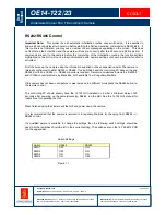
Page 9: ...d 24V to the zoom pin will cause the camera to zoom telescopic Applying a voltage of between 24V and 4V will cause the camera to zoom wide Removal of these voltages will cause the camera to stop zooming Focus The focus function is only available when the camera is in manual focus mode Applying a voltage of between 8V and 24V to the focus pin will cause the camera to focus far Applying a voltage of...

Page 10: ...focus mode If the Bi Polar Focus Far line is positive by 6 12V with respect to the Bi Polar Focus Near then the camera will focus far If the Bi Polar Focus Near line is positive by 6 12V with respect to the Bi Polar Focus Far then the camera will focus near Auto focus Applying a voltage of between 24V and 4V to the auto focus pin will cause the camera to go into auto focus mode This is the normal ...

Page 11: ...ach camera The controlling PC should already have the 14 122 GUI installed on it After a minimum delay of 3 seconds after powering up the cameras run the GUI See the 14 122 GUI manual for instructions for operating the GUI When finished using the camera exit the GUI and power down the cameras Important Information Note For users of multiple OE14 122 OE14 123 Pan Tilt Zoom PATZ cameras on a single ...

Page 12: ...camera module and some electronic components 5V for powering most of the IC s Isolated 5V to isolate some input circuitry as to prevent noise on the video line and as a reference voltage for tri state operation It separates tri sate bi polar and RS485 signals and sends them to the correct processing IC On the top side is the control and video processing circuitry process and amplifies the video si...

Page 13: ...F 014 0185 C9 CAP TANT 22U 10 019 9505 C11 CAP CER 10U 10V 1206 SM 019 9551 C16 C17 C18 C19 C20 C21 C24 C25 C26 C27 C30 C33 C35 CAP 3 TERMINAL 2200PF 014 0181 D1 DIODE SCHOTTKY 3A 40V 046 0501 D2 DIODE SOD106A 30V SM 046 0504 D3 DIODE BYD17D 1 5A 200V 046 0500 D4 D8 D9 DIODE BYD17D 1 5A 200V 046 0500 D5 D10 SUPPRESSOR TRANS SMBJ30 047 0014 D6 D11 SUPPRESSOR TRANS SMBJ15 047 0015 D7 D12 DIODE ZENER...

Page 14: ...me Ltd User Manual OE14 122 Colour Pan Tilt and Zoom Camera 5023 5 Page 14 of 14 Fault Finding Fault Finding The printed circuit boards in the camera contain surface mount and other components which are not user serviceable It is therefore strongly recommended that the camera be returned to Kongsberg Maritime for service or repair The camera contains 3 PCB s 14 122 6011 14 122 6012 and 14 122 6013...

Reviews: