JBA Explorer.lnk
OE14-122/23
Underwater Colour Pan, Tilt and Zoom Camera
colour
U
ser
Ma
nua
l
Manufacturing:
Airport Industrial Estate, Wick, Caithness, Scotland
tel:
+44 (0)1955 603606
fax:
+44 (0)1955 607520
Sales and Service:
Campus 1, Science and Technology Park, Aberdeen, Scotland
tel:
+44 (0)1224 226500 (24 hrs)
fax:
+44 (0)1224 226501
Kongsberg Maritime Ltd
User Manual:
OE14-122 Colour Pan, Tilt and Zoom Camera - 5023 –5
Page 8 of 14
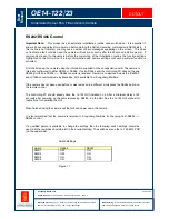
RS232/RS485 Control
Important Note:
This product has an automatic initialization routine once switched on. It is essential to
allow a 50 second delay after power up before starting the GUI and sending commands via RS232/485. If
this routine is not followed, you may see a number of error messages appearing on the screen. This does
not indicate a fault condition and the camera will function correctly after the 50 second initiation period. If
commands are sent to the camera before the completion of the initialization routine, the function settings
highlighted on the GUI will not be in synchronization with camera settings until each particular function is
activated.
First of all wire up the camera using the information supplied on the encapsulation card. The camera is
internally configured to either RS232 or RS485. If using RS485 and the controlling PC does not have a
RS485 port then a RS232 <-> RS485 converter is required. Recommend devices include the IC620A-F
and IC109A converters made by Black Box, both available from Kongsberg Maritime.
If the camera has not been used before or was last used in a different mode press the RS485 button on
the remote control.
The controlling PC should already have the 14-122 GUI installed on it. After a minimum delay of 50
seconds after powering up the camera/pressing RS485, run the GUI. See the 14-122 GUI manual for
instructions for operating the GUI.
When finished using the camera exit the GUI and power down the camera.
It is recommended that the camera is returned to Kongsberg Maritime for changing from RS232 <>
RS485 control.
If a qualified person is available to change the settings then the following switch settings should be
used. All other switches should be left in their current setting. The switches are on the 14-122-6012 PCB
(on the upper side).
Switch
Settings
Switch
RS485
RS232
SW2/1 OFF ON
SW2/2 OFF ON
SW2/3 ON
ON
SW2/4 ON
OFF
Figure 1.1


