Seatex AIS 100 Instruction Manual, rev. 5
Installation
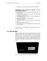
38
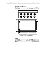
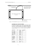
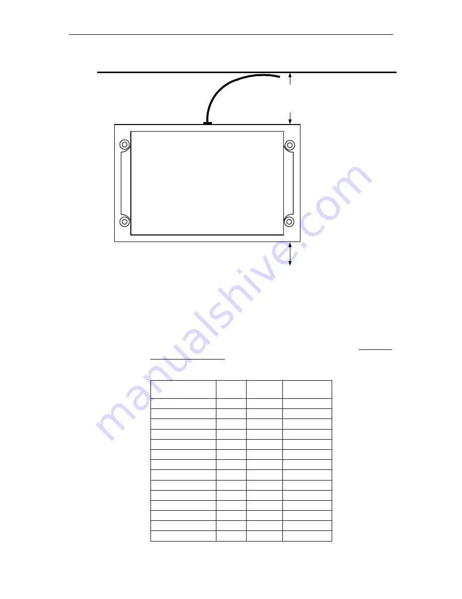
Seatex AIS 100 Connection Box
Top View
12
5mm
Recommended minimum
distance from rear side of
connection box to wall.
Interconnection cable from
transponder unit.
Ensure sufficient space for external
system interfaces.
Bulkhead
Figure 14 Recommended free space to rear side of connection box
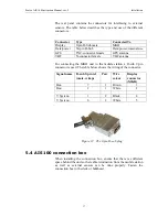
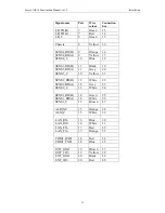
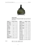
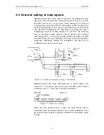
Connection box screw terminals
In the connection box, pins 37 and 38 are connected together, and pins
39 and 40 are connected together with a connection bridge (please
note that the + and GND are paired, so the numbering in the last row:
37, 39, 38 and 40 is correct!). If the power conductors are minimum
one square millimetre, they can be connected to pins 38 and 40 only.
Signal name
Pair
Wire
colour
Connection
box
Pilot_RD(B)
1
Black
1
Pilot_RD(A)
1
Brown
2
Pilot_TD(B)
2
Black
3
Pilot_TD(A)
2
Green
4
Pilot_C
3
Black
5
PI_RD(B)
4
Blue
6
PI_RD(A)
4
Black
7
PI_TD(B)
5
Grey
8
PI_TD(A)
5
Red
9
PI_C
3
Orange
10
LR_RD(B)
6
Brown
11
LR_RD(A)
6
Red
12
Summary of Contents for Seatex AIS 100
Page 1: ...Seatex AIS 100 Instruction Manual...
Page 2: ...Blank page...
Page 4: ...iv Blank page...
Page 8: ...viii Blank page...
Page 20: ...Seatex AIS 100 Instruction Manual rev 5 Operation 12 Blank page...
Page 40: ...Seatex AIS 100 Instruction Manual rev 5 Technical specifications 32 Blank page...
Page 92: ...Seatex AIS 100 Instruction Manual rev 5 External interfaces 84 Blank page...
Page 100: ...Seatex AIS 100 Instruction Manual rev 5 Maintenance 92 Blank page...
Page 104: ...Seatex AIS 100 Instruction Manual rev 5 Troubleshooting 96 Blank page...
Page 106: ...Seatex AIS 100 Instruction Manual rev 5 Parts list 98 Blank page...
Page 110: ...Seatex AIS 100 Instruction Manual rev 5 Appendix B Declaration of conformity 102 Blank page...


