Seatex AIS 100 Instruction Manual, rev. 5
External interfaces
47
6
EXTERNAL INTERFACES
6.1
External interfaces
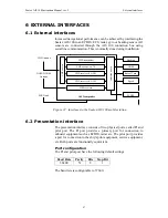
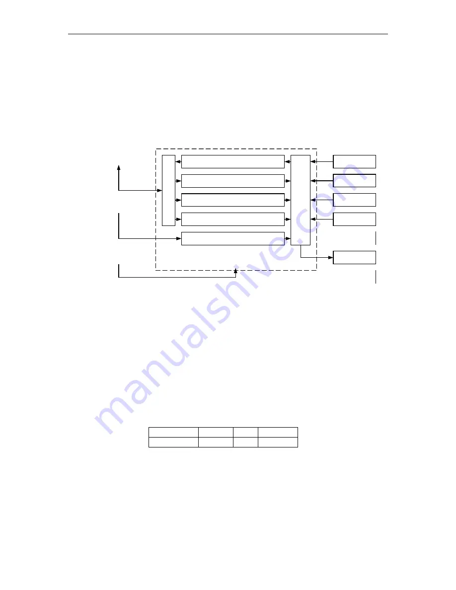
Increased navigational performance can be achieved by interfacing the
Seatex AIS 100 to an ECDIS, ECS, radar, gyro or heading sensor. All
sensors are connected through the AIS 100 connection box using
serial line communication. This is normally done during installation.
VHF-transmitter
VHF-receive ch. 70
VHF-receive ch. AIS 1
VHF-receive ch. AIS 2
GPS receiver
In
terface b
o
ard
VHF
switch
AIS Transponder
GNSS/DGNSS
Antenna
VHF Antenna
Heading
GNSS
Rate of Turn
Speed
ECDIS
MKD unit
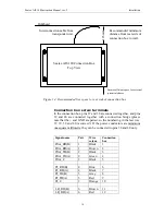
Figure 22 Interfaces to the Seatex AIS 100 mobile station
6.2
Presentation interface
The presentation interface consists of two physical ports, called PI and
pilot port. The PI port provides a primary port for connection to
onboard equipment such as ECDIS, radar etc. The pilot port provides
a port for connection to the ship's pilot equipment, service equipment,
etc. Both ports are functionally equivalent.
Port configuration
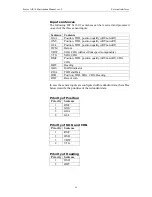
The PI and pilot port have the following default settings:
Baud Rate
Parity
Bits
Stop Bit
38400
N
8
1
The baud rate is configurable to 57600.
Summary of Contents for Seatex AIS 100
Page 1: ...Seatex AIS 100 Instruction Manual...
Page 2: ...Blank page...
Page 4: ...iv Blank page...
Page 8: ...viii Blank page...
Page 20: ...Seatex AIS 100 Instruction Manual rev 5 Operation 12 Blank page...
Page 40: ...Seatex AIS 100 Instruction Manual rev 5 Technical specifications 32 Blank page...
Page 92: ...Seatex AIS 100 Instruction Manual rev 5 External interfaces 84 Blank page...
Page 100: ...Seatex AIS 100 Instruction Manual rev 5 Maintenance 92 Blank page...
Page 104: ...Seatex AIS 100 Instruction Manual rev 5 Troubleshooting 96 Blank page...
Page 106: ...Seatex AIS 100 Instruction Manual rev 5 Parts list 98 Blank page...
Page 110: ...Seatex AIS 100 Instruction Manual rev 5 Appendix B Declaration of conformity 102 Blank page...

