Seatex AIS 100 Instruction Manual, rev. 5
External interfaces
54
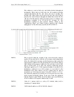
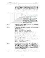
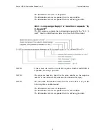
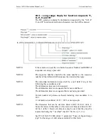
identifies the order of this sentence in the message, minimum value 1.
All sentences contain the same number of fields. Successive sentences
may use null fields for fields that have not changed, such as fields 4,
5, and 6.
NOTE 2
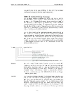
This sequential message identifier serves two purposes. It is both an
IEC 61162-1 "sequential message identifier field," and it is the
"sequence number" utilised by the ITU-R M.1371 in message types 6
and 12. The range of this field is restricted by ITU-R M.1371 to the
range of 0 to 3. This sequential message identifier and the destination
MMSI uniquely identifies a message. The sequential message
identifier may be reused after the "ABK" acknowledgement for that
sequence number is provided by the destination AIS unit. (See the
ABK-sentence formatter.)
NOTE 3
The MMSI of the AIS unit which is the destination of the message.
NOTE 4
The AIS channel that shall be used for the broadcast: 0 = no broadcast
channel preference, 1 = Broadcast on AIS channel A, 2 = Broadcast
on AIS channel B, 3 = Broadcast two copies of the message – one
copy sent on channel A and another copy sent on channel B.
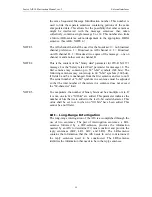
NOTE 5
This is the content of the "binary data" parameter for ITU-R M.1371
message 6, or the "Safety related Text" parameter for message 12. The
first sentence may contain up to 48 "6-bit" symbols (288 bits).
Following sentences may contain up to 60 valid "6-bit" symbols (360
bits), if fields 4, 5, and 6 are unchanged from the first sentence and set
to null. The actual number of "6-bit" symbols in a sentence must be
adjusted so that the total number of characters in a sentence does not
exceed the "82-character" limit.
NOTE 6
To encapsulate, the number of binary bits must be a multiple of six. If
it is not, one to five "fill bits" are added. This parameter indicates the
number of bits that were added to the last 6-bit coded character. This
value shall be set to zero when no "fill bits" have been added. This
cannot be a null field.
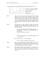
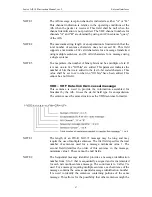
ACA – AIS regional channel assignment message
An AIS unit can receive regional channel management information
four ways: ITU-R M.1371 message 22, DSC telecommand received
on channel 70, manual operator input, and an ACA-sentence. The AIS
unit may store channel management information for future use.
Channel management information is applied based upon the actual
location of the AIS unit. An AIS unit is "using" channel management
information when the information is being used to manage the
operation of the VHF receivers and/or transmitter inside the AIS unit.
Summary of Contents for Seatex AIS 100
Page 1: ...Seatex AIS 100 Instruction Manual...
Page 2: ...Blank page...
Page 4: ...iv Blank page...
Page 8: ...viii Blank page...
Page 20: ...Seatex AIS 100 Instruction Manual rev 5 Operation 12 Blank page...
Page 40: ...Seatex AIS 100 Instruction Manual rev 5 Technical specifications 32 Blank page...
Page 92: ...Seatex AIS 100 Instruction Manual rev 5 External interfaces 84 Blank page...
Page 100: ...Seatex AIS 100 Instruction Manual rev 5 Maintenance 92 Blank page...
Page 104: ...Seatex AIS 100 Instruction Manual rev 5 Troubleshooting 96 Blank page...
Page 106: ...Seatex AIS 100 Instruction Manual rev 5 Parts list 98 Blank page...
Page 110: ...Seatex AIS 100 Instruction Manual rev 5 Appendix B Declaration of conformity 102 Blank page...

