background image

Seatex AIS 100 Instruction Manual, rev. 5

External interfaces

57

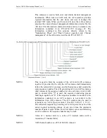
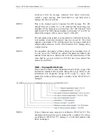
the external application's assessment of the combined reception of the
ABK-sentence and future VDM-sentences provided by the AIS via the
Presentation Interface. After receiving this AIR-sentence, the AIS
should broadcast a message 15 within 4 s, and the addressed AIS
should take no more than an additional 4 s to respond – a total of 8 s.

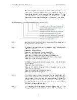
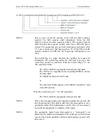
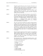
NOTE 1 

Identifies the first distant AIS being interrogated. Two messages can
be requested from the first AIS.

NOTE 2 

Examples of messages that may be requested from a distant mobile
AIS station include:
Message 3, Position Report,
Message 5, Ship Static and Voyage related data,
Message 9, Standard SAR Aircraft Position Report,
Message 18, Standard Class B Equipment Position Report,
Message 19, Extended Class B Equipment Position Report, and
Message 21, Aids-to-Navigation Report.

Examples of messages that may be requested from a distant AIS base
station include:
Message 4, Base Station Report,
Message 17, GNSS Broadcast Binary Message, (all available
corrections are requested),
Message 20, Data Link Management Message,
Message 22, Channel Management.

NOTE 3 

This field is used to request a message that has been further sub-
divided into alternative data structures. When requesting messages
with alternative data structures, this message subsection identifier
must be provided, so that the correct sub-division of the message data
is provided. If the message structure is not sub-divided into different
structures, this field should be null.

NOTE 4 

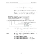
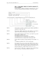
This identifies the second distant AIS being interrogated. Only one
message may be requested from the second AIS. The MMSI of the

Summary of Contents for Seatex AIS 100

Page 1: ...Seatex AIS 100 Instruction Manual...

Page 2: ...Blank page...

Page 3: ...Date Reason for revision 0 3 Draft versions 4 2003 03 03 Updated NMEA descriptions Man_instr_ais100_r5 5 2003 03 31 Minor update after internal revision Software versions This Instruction Manual appl...

Page 4: ...iv Blank page...

Page 5: ...back arrangements 10 2 4 Mobile station initialisation 10 2 5 Overview 11 3 DISPLAY PAGES 13 3 1 Main menu descriptions 13 3 1 1 Navigational status 13 3 1 2 Long range history 13 3 1 3 Voyage data 14...

Page 6: ...ription of installation setup 85 8 MAINTENANCE 89 8 1 General 89 8 2 Periodic maintenance 89 8 3 Repairs and modifications 89 8 3 1 Exchange of antenna cable 90 8 3 2 Exchange of GPS or VHF antennas 9...

Page 7: ...connector 35 Figure 11 Recommended free space to rear side of mobile station 36 Figure 12 Rear side of mobile station 36 Figure 13 The 9 pin D sub plug 37 Figure 14 Recommended free space to rear sid...

Page 8: ...viii Blank page...

Page 9: ...e guide for operation installation and maintenance of the Seatex AIS 100 system Great care has been taken to simplify the setup and operation of the system Please take the time to read this manual to...

Page 10: ...Related Message ACA AIS Regional Channel Assignment AIS Automatic Identification System ALR Alarm BIIT Built In Integrity Tests BS Base Station COG Course Over Ground DGPS Differential GPS DSC Digital...

Page 11: ...smit and receive AIS data AIS operates primarily on two dedicated VHF channels AIS 1 161 975 MHz and AIS 2 162 025 MHz Where these channels are not available regionally the AIS can be set to alternate...

Page 12: ...neous transmission of up to 500 stations Coverage The system radio coverage range is similar to other VHF applications and is dependent on the height of the antenna The propagation differs from that o...

Page 13: ...Hazardous cargo type Destination and ETA at Master s discretion Dynamic Data Position with accuracy indication and integrity status Time in UTC COG Course over ground SOG Speed over ground Heading Na...

Page 14: ...3 knots and changing course 2 sec Ship 23 knots 3 sec Ship 23 knots and changing course 2 sec All data input to the AIS mobile stations is based on the NMEA 0183 data protocol Messages sent on VHF are...

Page 15: ...r transmitting on all required frequencies and one DSC receiver The mobile station also incorporates a GPS receiver and a processor The internal GPS receiver which is capable of receiving differential...

Page 16: ...HF communication The antenna is connected to the mobile station using cables with attenuation less than 3 dB AIS 100 GPS antenna The GPS antenna is an L1 antenna receiving signals from all visible sat...

Page 17: ...fines its own reporting rate in accordance with its navigational mode speed and course The unit also selects its own data transmission slots This is the normal mode for operation in all areas but the...

Page 18: ...ion to triggering the alarm relay Malfunction type Malfunction source Tx malfunction ID 001 Tx frequency is not locked or Tx power is measured outside setting SWR 3 1 malfunction ID 002 SWR is measure...

Page 19: ...ALR Always Pressed more than once Displays the Long Range page SMS Always Pressed Displays the SMS Menu page MENU Always Pressed Displays the Main Menu page BACK Always Pressed Displays the previous p...

Page 20: ...Seatex AIS 100 Instruction Manual rev 5 Operation 12 Blank page...

Page 21: ...ain Menu page Press the MENU button on the MKD unit to access the main menu The program version is shown in the lower part of the page where 1 06 is the version number and zz the revision 3 1 1 Naviga...

Page 22: ...121 BELLA Name Callsign IMO Position COG SOG Choose from list OK Delete Delete All LR If a handled lr info req is selected the provided information will be displayed OK keeps the message and exits the...

Page 23: ...Identifier number IMO This is the vessel IMO number Type Type of vessel See Appendix A Vessel types Keel height over keel Total height of vessel in metres Static Data P14 Own Ship 1 3 Name ANNE BERIT...

Page 24: ...ut of the position for the AIS Mobile station antenna the Static data GPS page enables input of the vessel s main GPS GNSS antenna position 3 1 5 Dynamic data Dynamic Data P15 Own Ship 1 2 LAT 012 13...

Page 25: ...The Edit Current Region page enables the operator to change channels for the two AIS radio receivers The TxPower can only be set to High or Low If High is selected the transmission power is set to 12...

Page 26: ...VHF settings the transmitter can be turned off in this menu This option should only be used in situations where transmission would endanger the ship e g in war like situations piracy etc 3 1 8 Downpe...

Page 27: ...erfaces comply with NMEA 0183 Netw Settings P192 External ports IP adr 10 0 21 53 SubNet 255 255 255 0 Gateway 10 0 21 1 MAC MS 000 005 190 MAC LS 000 000 230 The Network page displays the network set...

Page 28: ...00 30 DSC Tx Msg4 59 59 DSC Rx Msg4 59 59 Displays the various messages received and transmitted on VHF The timestamp gives the elapsed time in minutes and seconds since the last event on the channel...

Page 29: ...e 3 2 Authorisation code entry This page will appear when modifying data protected by the security page Enter authorisation code PIN ABCDEFGHIJKLMNO PQRSTUVWXYZ1234 567890 In order to enter the Author...

Page 30: ...ges will change dynamically The lower part of the screen contains own vessel information in addition to status of alarms and events Name could be either MMSI number or name MMSI number is transmitted...

Page 31: ...HE SUNKEN VESSEL PIER II IN THE STRAUME STRAIT A message is displayed by selecting the sender and pressing the ENTER button Inbox P211 SANDPIPER 1 20 PLEASE BE AWARE OF THE SUNKEN VESSEL PIER II IN TH...

Page 32: ...re sent If deleted the next message will be displayed Predefined P23 Predefined Messages Departure Service request A predefined message can be entered in the Write Pred Msg A list of such messages wil...

Page 33: ...d Entry is similar to all other message entry with one exception For Broadcast messages no destination is selected Write Pred Msg P27 Departure READY FOR DEPARTURE ANY FINAL ISSUES ABCDEFGHIJKLMNO PQR...

Page 34: ...1230 utc lost 1200 Choose from list Acknowledge Acknowledge ALL When an alarm is selected the selected or all alarms can be acknowledged ALARMS P3 Own Ship3 ACK LR MSG 15 5 1230 Utc Lost 15 5 1200 Lo...

Page 35: ...rantee The liability of the manufacturer is limited to repair of the Seatex AIS 100 only under the terms and conditions stated in reference 1 and excludes consequential damages such as customer s loss...

Page 36: ...5 kHz Frequency range 156 165 MHz Transmitter power 2 W or 12 W nominal selectable AIS 1 Channel 87B 161 975 MHz AIS 2 Channel 88B 162 025 MHz DSC receiver 156 525 MHz Environmental specifications Enc...

Page 37: ...See Figure 6 Voltage input 24 V DC nominal range 18 35 V Seatex AIS 100 Connection Box top view 168mm 268mm 110mm 240mm 6 5mm 100mm Figure 6 Connection box dimensions Power Voltage input 24 V DC nomi...

Page 38: ...00 Instruction Manual rev 5 Technical specifications 30 VHF antenna Height 1400 mm Weight 2 2 kg with clamping brackets Colour Polyurethane lacquer white 1400mm 140mm 175mm Max 50mm min 30mm Figure 7...

Page 39: ...100 Instruction Manual rev 5 Technical specifications 31 GPS antenna Height 70 mm Diameter 78 mm Weight 400 g Voltage input 5 V DC from the mobile station 24mm 78mm 70mm Figure 8 GPS antenna and pole...

Page 40: ...Seatex AIS 100 Instruction Manual rev 5 Technical specifications 32 Blank page...

Page 41: ...connection to the MKD Connection box with cable for connection to the mobile station GPS antenna VHF antenna Installation distribution As installation costs may exceed the costs of the mobile station...

Page 42: ...he AIS mobile station Configuring the AIS mobile station Verifying that the unit works satisfactory in accordance with the IMO requirements In the following you will find detailed descriptions on how...

Page 43: ...colour Display connector MKD Bus 7 2 Brown 1 Bus 2 2 White 2 V System 1 1 Black 4 V System 6 1 White 5 Note The colour codes are according to Seatex supplied cable Figure 10 The Amphenol connector CAU...

Page 44: ...tation in a rack or onto the deck bulkhead ensure that the unit is properly secured Clamps are recommended to be used to secure antenna power and data cables connected to the mobile station Internal i...

Page 45: ...For connecting the MKD unit to the mobile station a D sub 9 pin connector is used The table below shows the wiring of the connector Signal name D sub 9 pin ref male crimp Pair Wire colour Display conn...

Page 46: ...ection box pins 37 and 38 are connected together and pins 39 and 40 are connected together with a connection bridge please note that the and GND are paired so the numbering in the last row 37 39 38 an...

Page 47: ...e 18 SENS3_RD B 11 Black 19 SENS3_RD A 11 Grey 20 SENS3_C 10 Yellow 21 SENS2_RD B 12 White 22 SENS2_RD A 12 Grey 23 SENS2_C 13 White 24 SENS1_RD B 14 Green 25 SENS1_RD A 14 White 26 SENS1_C 13 Brown 2...

Page 48: ...SENS3_C 40 10 Pilot_TD B 34 2 SENS2_RD A 25 12 Pilot_C 19 3 SENS2_RD B 8 12 PI_RD A 3 4 SENS2_C 41 13 PI_RD B 35 4 SENS1_RD A 26 14 PI_TD A 36 5 SENS1_RD B 9 14 PI_TD B 20 5 SENS1_C 42 13 PI_C 4 3 ALM...

Page 49: ...id stubs or make them as short as possible The common wire designated C is the signal ground reference and this wire shall be isolated from the outer shielding The outer cable shield shall be continuo...

Page 50: ...view of the horizon through 360 degrees The antenna should be installed safely away from interfering high power energy sources like radar and other transmitting radio antennas preferably at least 3 m...

Page 51: ...bles should be fitted with preventive isolation such as shrink stocking with glue to protect against water penetration into the antenna cable Coaxial cables should not be exposed to sharp bends which...

Page 52: ...ime synchronisation and computation of backup position fix The following should be taken into consideration during installation The GPS antenna must be installed where it has a clear view of the sky a...

Page 53: ...to 10 dB The coaxial cable between the antenna and the AIS mobile station should be routed directly in order to reduce electromagnetic interference effects GPS antenna cable lengths The GPS antenna c...

Page 54: ...the BIIT Alarm generated by the sensor part Alarm generated by the MKD An alarm could cause different actions taken by the system depending on the nature of the alarm An alarm generated by the BIIT co...

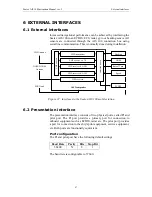
Page 55: ...board VHF switch AIS Transponder GNSS DGNSS Antenna VHF Antenna Heading GNSS Rate of Turn Speed ECDIS MKD unit Figure 22 Interfaces to the Seatex AIS 100 mobile station 6 2 Presentation interface The...

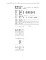
Page 56: ...rial port configuration parameters Output sentences The AIS is capable of generating and sending the IEC 61162 1 sentences on the presentation interface Sentence Content Transmission interval ABK Ackn...

Page 57: ...61162 1 sentences Sentence Content LRI Long range interrogation LRF Long range function identification Output sentences The Long Range reply from the AIS is accomplished through the use of four IEC 61...

Page 58: ...f non diff DTM Datum VBW SOG COG derived from speed components VTG SOG COG RMC Position TOD position quality diff non diff SOG COG HDT Heading GBS RAIM indicator ZDA TOD and Date OSD Position TOD SOG...

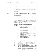
Page 59: ...nformation received in ITU R M 1371 messages 7 and 13 Upon reception of either a VHF Data link message 7 or 13 or the failure of messages 6 or 12 the AIS unit delivers the ABK sentence to the external...

Page 60: ...er number The following table lists the origins by message ID ITU R M 1371 Message ID Message Sequence Number source 6 sequential message identifier from ABM sentence IEC 61162 1 7 addressed AIS unit...

Page 61: ...more frequently than 4 s Retries stop when the appropriate acknowledgement See ITU R M 1371 messages 7 and 13 is received The AIS will make up to 4 broadcasts original broadcast plus three retires Th...

Page 62: ...E 5 This is the content of the binary data parameter for ITU R M 1371 message 6 or the Safety related Text parameter for message 12 The first sentence may contain up to 48 6 bit symbols 288 bits Follo...

Page 63: ...ether If provided by the AIS the ACS sentence shall immediately follow the related ACA sentence and both sentences shall contain the same sequence number The AIS generating ACA and ACS sentences shall...

Page 64: ...e AIS unit sends this sentence A value of 0 indicates that the parameters are not in use and a value of 1 indicates that the parameters are in use This field should be null when the sentence is sent t...

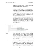
Page 65: ...18 Standard Class B Equipment Position Report Message 19 Extended Class B Equipment Position Report and Message 21 Aids to Navigation Report Examples of messages that may be requested from a distant A...

Page 66: ...apsulated data that can be sent in each slot and frame If the length of the message would exceed five slots or the AIS broadcast would exceed the limit of 20 RATDMA slot transmissions for the current...

Page 67: ...sentences may contain up to 60 6 bit symbols 360 bits if fields 4 and 5 are unchanged from the first sentence and set to null The actual number of 6 bit symbols in a sentence must be adjusted so that...

Page 68: ...field When the Control Flag is 0 the AIS responds if either The AIS is within the geographic rectangle provided and The AIS has not responded to the requesting MMSI in the last 24 hours and The MMSI d...

Page 69: ...LRI sentence and use the same sequence number The requestor process shall increment the sequence number each time a LRI LRF pair is created After 9 is used the process shall begin again from 0 The Lon...

Page 70: ...Information is available but not provided i e restricted access determined by ship s master LR1 Long range Reply with destination for function request A The LR1 sentence identifies the destination fo...

Page 71: ...ion identification characters See the LRF sentence NOTE 1 If the sentence is used the two fields Sequence Number and MMSI of responder are always provided NOTE 2 The sequence number should be the same...

Page 72: ...null field if any of the following three conditions exist The information item was not requested The information item was requested but is not available or The information item was requested but is n...

Page 73: ...from the bow stern port beam and starboard beam to the horizontal reference point on the ship for which the current position reports are valid The sum of A B is the length of the ship in metres and th...

Page 74: ...eceived on the VHF Data Link VDL using the 6 bit field type The structure provides for the transfer of long binary messages by using multiple sentences NOTE 1 The length of an ITU R M 1371 message may...

Page 75: ...s value shall be set to zero when no fill bits have been added This cannot be a null field VDO VHF Data link Own vessel message This sentence is used to provide the information assembled for broadcast...

Page 76: ...age transferred using multiple sentences and 63 valid characters for a message using a single sentence NOTE 5 To encapsulate the number of binary bits must be a multiple of six If it is not one to fiv...

Page 77: ...e TIME field type described in table 6 IEC 61162 1 The two fixed digits of seconds are not broadcast by the AIS and should be set to 00 The optional decimal point and associated decimal fraction shall...

Page 78: ...larm state Local alarm condition and status This sentence is used to report an alarm condition on a device and its current state of acknowledgement DTM Datum reference Local geodetic datum and datum o...

Page 79: ...ce character for user defined datums null field otherwise Subdivision character from IHO Publication S 60 Appendices B and C NOTE 3 Latitude and longitude offsets are positive numbers the altitude off...

Page 80: ...ange from 1 to 32 b The WAAS system has reserved numbers 33 64 to identify its satellites c The numbers 65 96 are reserved for GLONASS satellites GLONASS satellites are identified by 64 satellite slot...

Page 81: ...earth ellipsoid surface and mean sea level geoid surface mean sea level surface below the WGS 84 ellipsoid surface Utc of position Latitude Longitude and GPS quality is the only fields that are used...

Page 82: ...e more than one satellite system but for some reason one or more of the systems are not available then it may continue to report the positions using GNGNS and use the mode indicator to show which sate...

Page 83: ...all be provided in following GNS messages with talker IDs of GP GL etc These following GNS messages shall have the latitude N S longitude E W altitude geoidal separation mode and HDOP fields null This...

Page 84: ...ent corrections for the satellites used Null field when differential GLONASS is not used NOTE 3 HDOP calculated using all the satellites GPS GLONASS and any future satellites used in computing the sol...

Page 85: ...tracking of fixed target P positioning system ground reference Heading Heading status Vessel course Vessel speed and Speed units are used by the AIS RMC Recommended minimum specific GNSS data Time dat...

Page 86: ...Simulator mode N Data not valid NOTE 3 The positioning system Mode indicator field supplements the positioning system Status field field No 2 which shall be set to V invalid for all values of Mode in...

Page 87: ...fies the order of this message message number minimum value 1 For efficiency it is recommended that null fields be used in the additional sentences otherwise data is unchanged from the first sentence...

Page 88: ...N Data not valid The positioning system Mode indicator field shall not be a null field Course over ground degrees magnetic and Speed over ground km h are not used by the AIS ZDA Time and date UTC day...

Page 89: ...TXQ command Responses from the AIS mobile station uses the PSTXR command The proprietary messages comply with IEC 61162 1 and have the following structure P STX S Msg ID DATA FCS CR LF Field Definitio...

Page 90: ...r change the IMO number use the command PSTXS IMO nnnn FCS CR LF Field Description Range IMO Message ID identifying this sentence NA nnnn IMO number 0 to 1073741823 All fields are required and used Se...

Page 91: ...nterfaces 83 Field Description Range PORT Message ID identifying this sentence NA CCCC Name of serial port COM1 to COM32 bbbb Baud rate 1200 to 38400 p Parity N None E Even O Odd N E O d Data bits 5 8...

Page 92: ...Seatex AIS 100 Instruction Manual rev 5 External interfaces 84 Blank page...

Page 93: ...HEEL to select desired line and confirm with the ENTER button Edit the data field by selecting the symbol arrow with bar and enter in the end of the bottom line Type new data entry and confirm with EN...

Page 94: ...other The parameters necessary to customise are Setup procedure Name The vessel name Call The vessel call sign MMSI The Maritime Mobile Signal Identifier number IMO The vessel IMO number Type Type of...

Page 95: ...etup procedure Enter A B C D VHF Link P17 Ais Transceiver ChnA 2087 ChnB 2088 TxPower HIGH BW A Default BW B Default Transmitter TxON VHF link The AIS 100 Mobile station transmitting power is normally...

Page 96: ...interfaces comply with the NMEA 183 Setup procedure Change the baud rates accordingly Netw Settings P192 External ports IP adr 10 0 21 53 SubNet 256 256 256 256 Gateway 10 0 21 1 MAC MS 000 005 190 M...

Page 97: ...ectrical connections Cables should not be bent more than the minimum recommended bending radius and there should be no sharp bends on coaxial cables All cables should be fixed tight and rigid to their...

Page 98: ...uited with power on the GPS receiver within the unit can be damaged 8 3 2 Exchange of GPS or VHF antennas 1 Disconnect the power cable from the Seatex AIS 100 2 Dismount the failed antenna 3 Mount the...

Page 99: ...x AIS 100 1 Disconnect the power cable from the AIS 100 2 Disconnect the unit to be repaired from its cables and the rack and replace it with the spare unit 3 Connect all cables as they were on the or...

Page 100: ...Seatex AIS 100 Instruction Manual rev 5 Maintenance 92 Blank page...

Page 101: ...l power specifications section 4 3 If the transponder outputs an alarm the alarm condition can be read from the display 9 1 2 GPS and VHF antenna cable connections Typical problems when no GPS signal...

Page 102: ...vice 9 1 5 VHF transceiver failing If the VHF antenna and antenna cabling is OK and the MSG lamp on the front of the mobile station does not light green and amber vice versa this indicates incorrect d...

Page 103: ...in order to check for missing heading data Check that cable connections are correctly terminated in the connection box terminal screws 19 to 27 If correctly connected check the serial line communicati...

Page 104: ...Seatex AIS 100 Instruction Manual rev 5 Troubleshooting 96 Blank page...

Page 105: ...mounting The package consists of the following items A100 50 Seatex AIS 100 mobile station A100 51 Seatex AIS 100 MKD Minimum Keyboard Display A100 54 Seatex AIS 100 connection box including 3 m inte...

Page 106: ...Seatex AIS 100 Instruction Manual rev 5 Parts list 98 Blank page...

Page 107: ...No 18 Mob 83 Other Ships First digit1 Second digit1 First digit1 Second digit1 1 reserved for future use 0 All ships of this type 0 Fishing 2 WIG 1 Carrying DG HS or MP IMO hazard or pollutant catego...

Page 108: ...cond digit First digit Second digit 6 Passenger ships 6 Reserved for future use 6 Sailing 7 Cargo ships 7 Reserved for future use 7 Pleasure craft 8 Tanker s 8 Reserved for future use 8 Reserved for f...

Page 109: ...Seatex AIS 100 Instruction Manual rev 5 Appendix B Declaration of conformity 101 Appendix B Declaration of Conformity...

Page 110: ...Seatex AIS 100 Instruction Manual rev 5 Appendix B Declaration of conformity 102 Blank page...

Page 111: ...ower connector 40 datum 70 DGPS 2 Diagnostics 13 20 85 differential corrections 7 46 75 76 differential data 76 Downperiods 13 18 85 DSC 2 Dynamic data 16 E ECDIS 2 ECS 2 Edit Current Region 17 electr...

Page 112: ...22 23 24 25 P PI 2 pin layout data power connector 40 polled 9 10 polled mode 10 Port configuration 47 49 PPS 2 Predefined messages 25 presentation interface 47 48 product safety 27 PWR 2 R range 4 8...

Page 113: ...Seatex AIS 100 Instruction Manual rev 5 Index 105 Voyage Data 13 14 21 85 VTS 3 W warranty 27 Z Zone 17 18...

Reviews: