INSTALLATION MANUAL
20221594 / B
iii
Contents
1
INTRODUCTION ................................................................5
2
INSTALLATION..................................................................5
2.1
Mechanical installation ........................................................5
2.2
Cabling .............................................................................5
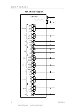
GI51 Block diagram .......................................................6
2.3
Dip switch settings..............................................................7
2.4
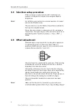
Interface setup procedure....................................................8
2.5
Offset adjustment...............................................................8
2.6
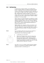
Calibration.........................................................................9
2.7
Initial heading and heading change test ............................... 10
2.8
S9 Steering lever.............................................................. 11
3
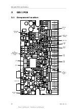
GI51 PCB ........................................................................12
3.1
Component location .......................................................... 12
3.2
Terminal description ......................................................... 13
TB1, Power................................................................. 13
TB2, Sin/Cos Out ........................................................ 13
TB3, Synchro In .......................................................... 13
TB4, NFU ................................................................... 13
TB5, Step Out............................................................. 13
TB6, Step In............................................................... 14
TB7 and TB8, NMEA..................................................... 14
TB9, RGC proprietary................................................... 14
TB10, LOG ................................................................. 14
TB11, Radar ............................................................... 14
TB12, Selector ............................................................ 15
4
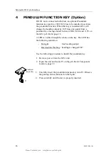
PENDULUM FUNCTION KEY (OPTION).............................16
5
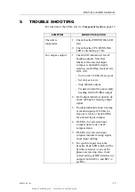
TROUBLE SHOOTING.......................................................17
5.1
LED indicators.................................................................. 18
6
SPARE PARTS..................................................................19
7
TECHNICAL SPECIFICATIONS .........................................20
7.1
Hardware ........................................................................ 20
7.2
Supply ............................................................................ 20
Busse-Yachtshop.de info@busse-yachtshop.de

