Chapter 10 RA83/84/85/93/94/95 Series
Technical Reference
Operation Manual
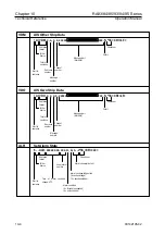
10.3.2 Radar System Data
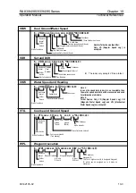
RSD
Radar System Data
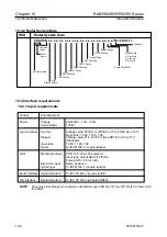
$ RA RSD, x.x, x.x, x.x, x.x, x.x, x.x, x.x, x.x, x.x, x.x, x.x, a, a *hh <CR><LF>
10.4 Interface requirements
10.4.1 Input requirements
Sentence
format
Talker
device
VRM 1 Range
Origin 1 Range
EBL 1 Bearing
Display Mode
C: Course Up
H: Head Up
N: North Up
Origin 2 Range
Checksum
Cursor Bearing
EBL 2 Bearing
Start of sentence
Origin 2 Bearing
VRM 2 Range
Cursor Range
Display Range
Range Unit (K/N/S)
Origi
Feature Characteristics
Power
Voltage
24/32VDC, -10%, +30%
Consumption
170
W
Gyro compass Synchro
Voltage value: 50VAC or /-10%, 50/60 Hz+/-10%
Gear ratio: 1:360, 1:180, 1:90
Stepper
Voltage value: 21.6 to 38.5 V (See NOTE) or 63 to 77 V
(Standard)
Gear ratio
1:360, 1:180, 1:90
Serial
To IEC61162-1 via opto-isolator
LOG
Mechanical input
PRR: 100, 200, 400 pulse/nm
Input type: opto-isolator (5V/5mA)
Pulse width: 100 ms (min)
Electronic input
Same as above
Serial input
To IEC61162-1 via opto-isolator
Serial interface Signal standard
To IEC 61162-1 via opto-isolator
AIS interface
Signal standard
To IEC 61162-2 via floated RS422
NOTE:
Changing Link settings are required on the Main Logic PCB for J721 to J725. Refer to Para. 4.6.6
for detail.
10-6
93142105-02

