Chapter 10 RA83/84/85/93/94/95 Series
Technical Reference
Operation Manual
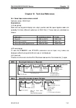
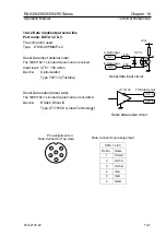
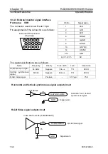
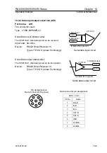
10.4.5 Radar Signal input/output
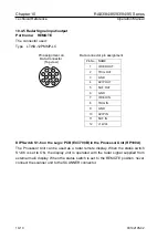
Port name: REMOTE
The connector used:
Type LTWU-12PMMP-LC
1
2
3
4
5
6
8
9
12
10
11
7
Pin assignment on
Data Connector
(Top view)
Data connector pin assignment
Pin No.
NAME
1 VIDEO
OUT
2 TRIG
OUT
3 GND
4 AZIP
OUT
5 SHF
OUT
6 GND
7 VIDEO
IN
8 TRIG
IN
9 GND
10 AZIP
IN
11 SHF
IN
12 +12Vdc
DIP Switch S1-6 on the Logic PCB (E47-700B) in the Processor Unit (RP100A)
The Processor Unit can be used as a radar remote display. When the status switch
S1-#6 is set to ON, the display unit is operated with the radar signal supplied from
external main display. When the status switch is set to the REMOTE position, never
connect the scanner unit to the SCANNER connector.
10-10
93142105-02

