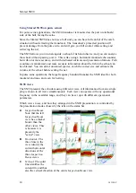
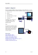
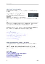
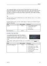
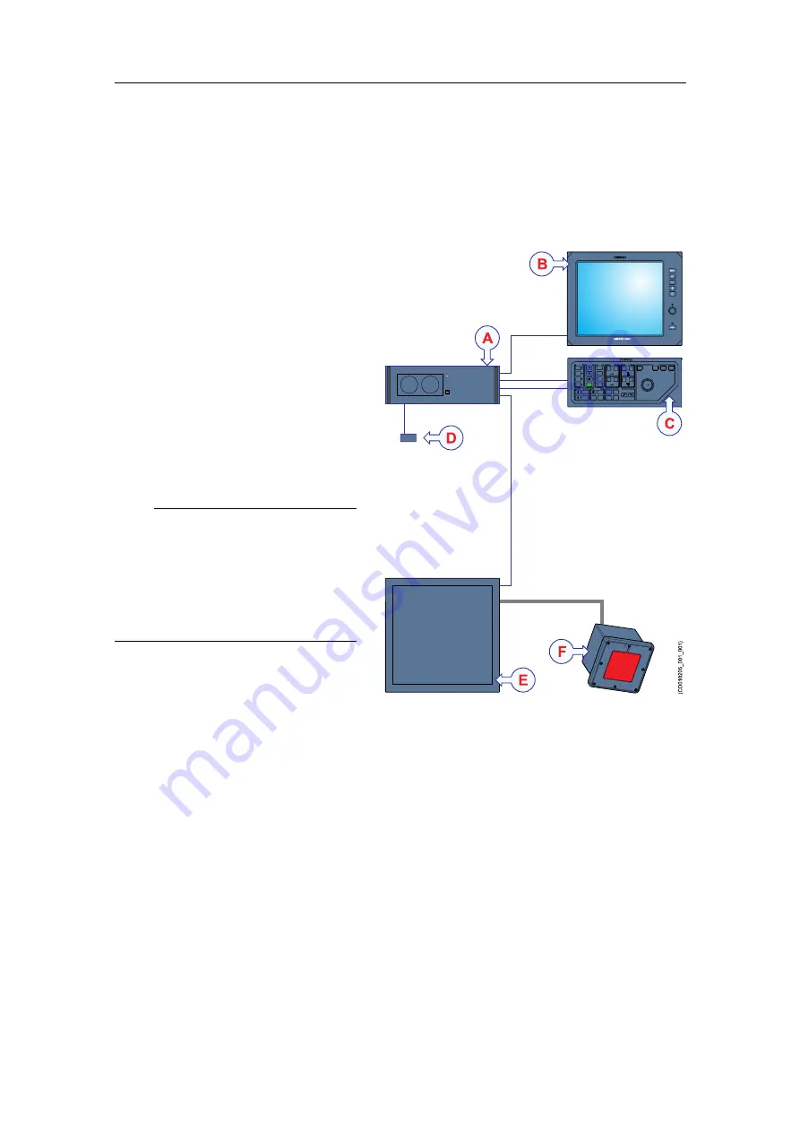
background image

18

381298/C

System diagram

The system diagram identifies the main components of a basic SN90 system, as well as
the connections between the units. Interface capabilities and power cables are not shown.

SIMRAD

PWR

MENU

SIMRAD

SIMRAD SN90

(CD010205_001_001)

B

C

D

E

A

F

A

Processor Unit

B

Display

C

Operating Panel

D

Operating Panel Power Supply

E

Transceiver Unit

F

Transducer

The display is not a standard part
of the SN90 delivery. This is
a commercial item that can be
purchased locally.

Note

Each transducer installation must be
designed to fit the vessel’s hull shape
and characteristics. The installation
method and the cable penetration
must be approved by the relevant
maritime authority.

Related topics

System description, page 13
Display description, page 19
Processor Unit description, page 20
Transceiver Unit description, page 21
Operating Panel description, page 22
Operating Panel Power Supply description, page 22
Transducer description, page 23
Performance specifications, page 246

Simrad SN90

Summary of Contents for Simrad SN90

Page 1: ...Simrad SN90 Purse Seine and Trawl sonar www simrad com TECHNOLOGY FOR SUSTAINABLE FISHERIES Installation Manual ...

Page 2: ......

Page 3: ...l Sonar The information is intended for qualified personnel such as naval architects shipyard engineers and skilled workers For information about the practical use of the product refer to the Simrad SN90 Operator manual and or the Simrad SN90 Reference manual Caution As a safety precaution you must never power up the SN90 when the ship is in dry dock The transducer will be damaged if it transmits ...

Page 4: ...proper use or maintenance may cause damage to the equipment and or injury to personnel The user must be familiar with the contents of the appropriate manuals before attempting to operate or work on the equipment Kongsberg Maritime disclaims any responsibility for damage or injury caused by improper installation use or maintenance of the equipment Disclaimer Kongsberg Maritime AS endeavours to ensu...

Page 5: ...nstallation requirements 32 Supply power requirements 32 Uninterruptible Power Supply UPS requirements 32 Cables and wiring requirements 33 Compass deviation requirements 33 Noise sources 34 Dry docking requirements 34 Requirement for classification approval 34 Network security 35 Support information 36 PREPARATIONS 38 Installation summary 39 About installation drawings 40 Tools equipment and cons...

Page 6: ... noise 54 Contributing factors 54 Self noise 56 Ambient noise 58 Electrical noise 58 Reverberation 59 Some means to reduce acoustic noise 59 Vessel coordinate system 61 INSTALLING THE TRANSDUCER 64 Installation summary 65 Transducer installation principles 67 Installing the transducer for use on purse seiners 67 Installing the transducer for use on trawlers 70 Installing the transducer for navigat...

Page 7: ...Operating Panel 120 Cutout drawing for Operating Panel installation 121 Installing the Operating Panel Power Supply 122 Installing the Transceiver Unit 123 Location of the mounting brackets 126 Installation of the mounting brackets 127 Transceiver Unit grounding 128 CABLE LAYOUT AND INTERCONNECTIONS 129 Read this first 130 Cable plans 131 Topside cable plan 132 Sonar room cable plan 133 List of SN...

Page 8: ...le using IEC C13 inline socket 160 Grounding cable 161 Communication and power cable for the Operating Panel 162 RS 232 serial line connection using three wires 163 RS 232 serial line connection using five wires 164 RS 422 serial line connection using five wires 165 RS 232 used as synchronization trigger input or output 166 Moxa CP114EL I Serial line adapter 167 RJ45 High speed Ethernet cable 1000...

Page 9: ...ipheral devices 204 Setting up the input from a navigation system 204 Setting up the input from a Motion Reference Unit MRU 208 Setting up the SN90 in a synchronized system 209 IP addressing and UDP port principles 212 Powering off the SN90 215 Installation remarks 216 DRAWING FILE 218 About the drawings in the drawing file 219 396280 Transceiver Unit outline dimensions 220 385609 Processor Unit o...

Page 10: ...fter unpacking 265 Packing instructions for storage or shipping 266 Storage after use 267 Cleaning an electronic cabinet or unit 268 Cleaning a mechanical or electromechanical unit 269 Handling instructions for printed circuit boards and electronic modules 270 Circuit board unpacking and handling 270 Returning a printed circuit board or an electronic module to Kongsberg Maritime 272 About Electros...

Page 11: ...nar operation Installation instructions You must follow the instructions in this manual to ensure optimal performance As a guide installation procedures are presented in the order they must be done The equipment described in this manual includes the complete system with relevant cabinets Units provided locally by the customer installation shipyard or local representative are not described The manu...

Page 12: ... generic outline dimension and or productions drawings are provided in the Drawing file chapter Drawings may also be downloaded in PDF and or DWG formats from our website http www simrad com sn90 On line information All end user manuals provided for operation and installation of your Simrad SN90 can be downloaded from our website http www simrad com sn90 Our website will also give you information ...

Page 13: ... 12 System description page 13 Key features page 16 System diagram page 18 System units page 19 Scope of supply page 24 General safety rules page 31 Installation requirements page 32 Network security page 35 Support information page 36 SN90 ...

Page 14: ...If you believe that something has broken down contact your local dealer They will be able to assist A list of all our dealers is provided on our website http www simrad com If you are unable to contact a dealer observe the support information in this publication When you wish to switch off the SN90 You must NEVER switch off the SN90 by means of the on off switch on the Processor Unit You must ALWA...

Page 15: ... on trawlers Trawlers have for many years relied on high resolution echo sounders such as the Simrad ES70 to find and estimate their catch The disadvantage with echo sounders is the fact that they look straight down The SN90 offers the high resolution of an echo sounder but also a large horizontal range that allows you to find fish even close to the bottom from a distance of several hundred meters...

Page 16: ... catch the correct size and estimate the volume of the school before setting the net In purse seine operations the large frequency bandwidth makes the SN90 ideal for both mackerel and tuna and even for herring SN90 views The SN90 presents the echo data using different views All information from one single ping is shown in all views simultaneously Each view can operate with any operational frequenc...

Page 17: ...nge the physical size any view by clicking on the view border and then drag it to create a larger rectangle Note that the size of the other views will be reduced accordingly Specifications and functionality The Simrad SN90 is a unique sonar both in design and functionality The composite transducer and the transceiver each uses 256 individual channels for transmission and reception A large frequenc...

Page 18: ...both trawlers and purse seiners For use on trawlers the transducer is mounted on the vessel s bow in a forward looking position It is well protected against acoustic noise from hull machinery and propellers The high resolution and long range allows you to detect and investigate single fish and schools even those close to the bottom from a distance of several hundred meters For use on purse seiners...

Page 19: ...381298 C 17 Define and save your own user settings Clear and easily comprehensive sonar data Related topics Performance specifications page 246 SN90 ...

Page 20: ...ndard part of the SN90 delivery This is a commercial item that can be purchased locally Note Each transducer installation must be designed to fit the vessel s hull shape and characteristics The installation method and the cable penetration must be approved by the relevant maritime authority Related topics System description page 13 Display description page 19 Processor Unit description page 20 Tra...

Page 21: ...ight and angle Any commercial display can be used with the SN90 Purse Seine and Trawl Sonar provided that the display meets the minimum requirements Note The display is not a standard part of the SN90 delivery This is a commercial item that can be purchased locally The chosen display must be designed for maritime use and it must meet the minimum performance specifications You must also make sure t...

Page 22: ...ritime to suit the SN90 requirements The Processor Unit cabinet is placed on shock absorbers The Processor Unit is based on the Microsoft Windows 7 operating system The Processor Unit offers multiple USB ports for use with future software upgrades These USB ports also allow you to export screen captures and recorded data from the SN90 Note The operating system has been modified to make the Process...

Page 23: ...ical transceiver boards are used The unit also holds a power supply an Ethernet switch and a large capacitor bank An Ethernet cable is used for communication with the Processor Unit on the bridge The transducer cables are plugged into the side wall of the Transceiver Unit cabinet using a special multi connector The connectors for power and interfaces are located at the bottom of the cabinet Note T...

Page 24: ...and buttons provided are not used by the SN90 Related topics System diagram page 18 Installing the Operating Panel page 120 Cutout drawing for Operating Panel installation page 121 204688 Operating Panel outline dimensions page 227 Interface specifications page 248 Weight and outline dimensions page 249 Power requirements page 251 Environmental requirements page 253 Operating Panel Power Supply de...

Page 25: ...n or cleaning Any holes and or scratches in the transducer surface will allow water to penetrate the transducer If a leak occurs the transducer must be replaced A transducer must always be handled as a delicate item Wrongful actions may damage the transducer beyond repair Observe these transducer handling rules Do not activate the transducer when it is out of the water Do not lift the transducer b...

Page 26: ...tional When you unpack the parts provided with the SN90 delivery verify that the following items are included Basic items Item Order number In the box Transceiver Unit 383022 Transceiver Unit Power cable Ethernet cable 1 5 m Processor Unit 382908 Computer Enix 2670 Operating Panel Power Supply Power cable Serial line connectors and adapters Video cable Documentation Software Operating Panel SH8 20...

Page 27: ...ucer 382817 Transducer Transducer cable Length of transducer cable 25 m The transducer plug is NOT fitted Cable glands for sealing plate is included Transducer options Item Order number In the box Sealing plate 382838 Sealing plate Mounting kit 381849 Mounting house Clamping frame Mounting hardware Operational software Operational software is provided on a suitable media If the Processor Unit is p...

Page 28: ... suggest that you purchase a large high resolution display Kongsberg Maritime may provide a suitable display Consult your local dealer or agent for more information Item Order number In the box Display 335513 Display Hatteland JH19T14 19 inch 1280 x 1024 Power cable Documentation Mounting hardware 339785 Uninterruptible Power Supply UPS It is important to ensure continuous operation of the SN90 in...

Page 29: ...on In most cases a suitable sensor is already installed on the vessel A global positioning system GPS with a fitting output format can also be used The speed log interface requirements are Serial line Standard NMEA 0183 telegram format Ethernet Standard NMEA 0183 telegram format Course gyro In order to operate correctly the SN90 requires input from a course gyro A course gyro is not a part of the ...

Page 30: ... contains a 10 bytes long message Kongsberg Maritime may provide a suitable motion reference unit Consult your local dealer or agent for more information Item Order number In the box Motion Reference Unit MRU 390313 Seatex MRU D Documentation Additional optional items Additional items are available for the SN90 Some are optional for SN90 operation These may for example simplify the installation or...

Page 31: ...sult your local dealer or agent for more information Item Order number In the box Display 335513 Display Hatteland JH19T14 19 inch 1280 x 1024 Power cable Documentation Mounting hardware 339785 Secondary Operating Panel A secondary Operating Panel may be connected to the SN90 Processor Unit This may be useful in conjunction with a secondary display if you wish to control the SN90 from two differen...

Page 32: ...osition and provide cursor and marker latitude and longitude In addition to navigational data the GPS may also be used for the input of speed log information Note Most positioning systems can provide the current present course information but this data is generally too inconsistent to provide a stable SN90 presentation Simrad SN90 ...

Page 33: ... others that maintenance or installation work is in progress on the system 2 For safety reasons two persons must always be present during troubleshooting with power ON 3 Read and understand the applicable first aid instructions related to electric shock 4 Whenever maintenance is in progress it is essential that a first aid kit is available and that all personnel are familiar with the first aid ins...

Page 34: ...itions Uninterruptible Power Supply UPS requirements Observe these requirements related to the Uninterruptible Power Supply UPS It is important to ensure continuous operation of the SN90 independent of varying quality of the vessel s mains supply The use of uninterruptible power supplies is therefore required Uninterruptible power supply units are not included in the standard SN90 delivery These i...

Page 35: ...re lengths using conduits and or cable trays Note that the cables must not be installed in the vicinity of high power supplies and cables antenna cables or other possible sources of interference All transducer cables must be run in steel conduits For more detailed information about cables and wiring refer to the basic cable requirements Compass deviation requirements SN90 units that are installed ...

Page 36: ...cial considerations must be made prior to dry docking Make sure that ample clearance is provided under the transducer when you are placing the vessel in dry dock Do not place supporting blocks or structures in the vicinity of the transducer The location of the transducer must be noted on the vessel s docking plan for future reference Prior to dry docking power down the SN90 Disengage the circuit b...

Page 37: ...ystem installation on any vessel we can not estimate the threat level and the need for network security For this reason we can not accept responsibility for network security Systems provided by Kongsberg Maritime are regarded as stand alone offline systems even though they may be connected to a network for sensor interfaces and or data distribution Note No network safety applications are installed...

Page 38: ...mrad support simrad com Spain Company name Simrad Spain Address Poligono Partida Torres 38 03570 Villajoyosa Spain Telephone 34 966 810 149 Telefax 34 966 852 304 Website http www simrad es E mail address simrad spain simrad com France Company name Simrad France Address 5 rue de Men Meur 29730 Guilvinec France Telephone 33 298 582 388 Telefax 33 298 582 388 Website http www simrad fr E mail addres...

Page 39: ...3 2201 3359 Website http www simrad com E mail address simrad asia simrad com Korea Company name Kongsberg Maritime Korea Ltd Address 1101 Harbor Tower 113 1 Nampodong 6 Ga Jung Gu Busan 600 046 Korea Telephone 82 51 242 9933 Telefax 82 51 242 9934 Website http www simrad com E mail address simrad korea simrad com Related topics Important page 12 Troubleshooting the Transceiver Unit if it fails to...

Page 40: ...40 Tools equipment and consumables required for SN90 installation page 41 Personnel qualifications page 41 Location of hardware units on the bridge page 42 Sonar room requirements page 47 Where to install the transducer page 51 Acoustic noise page 54 Vessel coordinate system page 61 Simrad SN90 ...

Page 41: ...ary considerations must be taken to avoid acoustic and electric disturbances Note This information in this document must be regarded as general guidelines and recommendations only The installation shipyard must design and manufacture installation hardware to fit the transducer to each individual vessel Whenever required the installation shipyard must also have the transducer installation approved ...

Page 42: ...or the physical installation of the SN90 must be approved by the vessel s national registry and corresponding maritime authority and or classification society Such approval must be obtained before the installation can begin The shipowner and shipyard doing the installation are responsible for obtaining and paying for such approval Kongsberg Maritime offers free advice for installation planning Pro...

Page 43: ...nd consumables required for electrical installations Note Whenever specific consumables or special tools or test instruments are required these are identified in the relevant procedure s Personnel qualifications The installation of the SN90 is a demanding task It is very important that the personnel involved in the installation tasks are competent and experienced craftsmen As a minimum the followi...

Page 44: ...must be decided with regard to basic installation requirements Observe the following basic requirements 1 Safe navigation The physical location of each hardware unit must not in any way have a negative effect on the navigation of the vessel Observe the compass safe distance for each individual unit 2 Operational requirements The location of each physical unit must be based on the ergonomically cor...

Page 45: ... Description Length C1 This is a commercial cable It is not supplied with the SN90 delivery and must be obtained locally C2 This is a commercial cable It is not supplied with the SN90 delivery and must be obtained locally C3 Power cable 1 7 m C4 Power cable 1 8 m C5 Power cable 1 78 m C6 This cable must be provided by the installation shipyard C7 This cable must be provided by the installation shi...

Page 46: ...he Processor Unit to the Transceiver Unit using the existing local area network Selecting the best location for the display For best readability the display must be located so that it is best protected from glare and with the correct height and angle In most cases the display may be Panel mounted Desktop mounted Bulkhead mounted Overhead mounted Tip If several displays are mounted on the bridge fo...

Page 47: ... Selecting the best location for the Operating Panel The Operating Panel contains all necessary control functions for normal operation of the SN90 The Operating Panel must be mounted in a nearly horizontal position and within easy viewing range of the display We recommend that the Operating Panel is positioned in the same physical direction as the display so that up on the operating panel is the s...

Page 48: ... end that the ventilation is adequate Compass safe distance The compass safe distance for the Operating Panel Power Supply has not been defined If it is installed close to the Processor Unit the compass safe distance required by the Processor Unit gives sufficient protection Simrad SN90 ...

Page 49: ...be possible to close all watertight hatches and or doors to the sonar room to maintain the vessel stability and safety The physical size of the sonar room must be limited so that in the event of a major leak the flooding of the sonar room will not induce instability or cause the vessel to capsize or sink Ensure that all watertight decks and bulkheads are inspected periodically to verify that there...

Page 50: ...ols and equipment can be removed without being disassembled 5 All cables leading in and out of the room must be run in steel conduits These steel conduits must reach up and above the freeboard deck Important The physical distance between the Transceiver Unit and the transducer is limited by the length of the transducer cables Insulation heating and ventilation The bulkheads in the sonar room must ...

Page 51: ...l installations cables and communication The electrical installations in the sonar room must meet minimum requirements to provide suitable lights and supply power 1 If the cables between the sonar room equipment and other system units located in different compartments on the vessel pass through hatches or areas where they may be damaged they must be run through conduits minimum 2 conduit is recomm...

Page 52: ...t must be connected to the vessel s bilge pump system If this is not possible a separate bilge pump for the sonar room must be installed Once the installation has been completed the sonar room must be suitably decked without restricting access to the equipment and the cables Simrad SN90 ...

Page 53: ...ing on the hull design Mount the transducer deep In order to achieve the best possible SN90 performance mount the transducer as deep as possible under the vessel s hull Consider the situations when the vessel is unloaded and when it is pitching in heavy seas There are several reasons for this 1 The upper water layers of the sea contain a myriad of small air bubbles created by the breaking waves In...

Page 54: ... of sealing compound sharp edges protruding bolts or bolt holes without filling compound will create noise Stay far away from the propellers The propulsion propellers is the dominant noise source on most vessels The noise is transmitted through the sea water and may often reduce the performance of your SN90 system For this reason the transducer must be placed far away from the propellers which mea...

Page 55: ...ividually in order to find the best compromise In general the most important factor is to avoid air bubbles in front of the transducer face For this reason the recommended transducer location is normally in the fore part of the hull well ahead of the noise created by the bow wave The maximum distance from the bow is normally equal to one third of the total water line length of the hull If the vess...

Page 56: ...quality and properties of the transmitted signal The quality of the receiving system The operational settings made during operation The properties of the target s The signal to noise ratio The majority of these factors can neither be controlled nor improved by means of installation methods or transducer locations The quality and properties of the transmitting and receiving systems are key factors ...

Page 57: ...ed into the following types of noise Self noise Ambient noise Fishing gear noise Electrical noise Reverberation CD010205_900_001 A The transducer can pick up noise from Biological disturbances Interference Cavitation Propeller noise Flow noise Acoustic noise from other hydroacoustic systems B The transducer cable is long and may pick up electric noise from generators pumps cooling systems etc C Th...

Page 58: ...p structure and the transducer mountings Water borne noise through the hull into the water to the transducer Electric noise Modern vessels are normally equipped with a lot of electric instruments such as hydroacoustic systems radars navigation systems and communication equipment Any electric instruments may in some cause electrical interference and noise International regulations and certification...

Page 59: ...c domain Flow noise Every object that moves through water will disturb the medium and it will cause friction in the water The friction zone is called the flow boundary layer The flow in this boundary layer may be laminar or turbulent The laminar flow is a nicely ordered parallel movement of the water The turbulent flow is a disorderly flow pattern full of eddies CD010203_300_010 A Turbulent flow B...

Page 60: ... bubbles seismic disturbances waves boundary turbulence etc Biological noise Fish mammals etc Man made noise Other vessels interference Precipitation noise In some areas where many vessels are operating together the engine and propeller noise from other vessels might be disturbing Interference from hydroacoustic instruments located in other vessels may also be a limiting factor The sea noise is as...

Page 61: ...rock mud sand Your current tilt setting will also have an effect on the reverberation The echo from the sea surface will vary with the current sea state and your current tilt setting CDCD010202_301_001 The illustration demonstrates how the bottom and the sea surface return echoes back to your sonar transducer In situation A you will be able to identify the upper school of fish but the lower school...

Page 62: ...ansducer must be as smooth as possible Be especially aware of bilge keels and zinc alloy anodes The keel should be rounded off without sharp edges Important No extruding objects or any abrupt transitions should appear Reducing machinery noise The transducer must be installed as far away from the engine room as possible The main engine and relevant auxiliary engines and equipment should be fixed to...

Page 63: ... transducer to the transceiver as possible Try to terminate the conduit as close to the transducer and transceiver as possible Make sure that all units are properly grounded as this is important to avoid electrical noise You must use shielded cables with correct grounding Separate SN90 cables from other cables with heavy currents or transients Place all high voltage power cables in metal conduits ...

Page 64: ...sitive value for Y means that a sensor or a reference point is located on the starboard side of the origin D C The Z axis is vertical and in parallel with the mast A positive value for Z means that a sensor or a new reference point is located under the origin D D Origin Coordinate system origin The origin is the common reference point where all three axis in the vessel coordinate system meet All p...

Page 65: ...y systems the vessel heading is also a critical measurement Y Z X CD010101_300_021 In this example a second reference point has been established It is defined with three positive offset values for X Y and Z All values are positive because the new reference point is in front of and below the origin and on the starboard side The accuracy of the three numerical values for X Y and Z defines the accura...

Page 66: ...81298 C Installing the transducer Topics Installation summary page 65 Transducer installation principles page 67 Transducer cables installation principles page 82 Installation procedures page 88 Simrad SN90 ...

Page 67: ...ducer must always be handled as a delicate item Wrongful actions may damage the transducer beyond repair Observe these transducer handling rules Do not activate the transducer when it is out of the water Do not handle the transducer roughly avoid impacts Do not expose the transducer to direct sunlight or excessive heat Do not use high pressure water sand blasting metal tools or strong solvents to ...

Page 68: ...it 12 If relevant connect the transducer cable to the large transceiver connector 13 If your vessel will operate in waters with a lot of marine growth consider applying a thin layer of anti fouling paint to the transducer face Related topics Transducer installation principles page 67 Transducer cables installation principles page 82 Determining the location and installation angles of the transduce...

Page 69: ...awlers page 70 Installing the transducer for navigational use page 73 Placing the transducer in the vessel coordinate system page 76 Watertight integrity page 81 Installing the transducer for use on purse seiners When used on a purse seiner the physical installation of the SN90 transducer is made by designing a blister or keel box For purse seining use the transducer must be installed facing the s...

Page 70: ... not allow the hull to create a shadow for the SN90 beams when minimum tilt is chosen in the user interface Note Keep in mind the default start location of the transducer all rotation angles set to 0 zero means that the transducer face is horizontal pointing straight down with the orientation mark arrow pointing forward Lifting the transducer to the requested angle will always require a positive r...

Page 71: ...ashers a rubber gasket and a packing nut The sealing plate can be purchased from Kongsberg Maritime or you can manufacture it yourself based on the production drawings available http www simrad com sn90 You can use a sealing plate in combination with a steel conduit or you can use it by itself Note If you only use a sealing plate to bring the transducer cables through the hull the compartment dire...

Page 72: ... vessel s hull The same blister or hull box may also be used for other sonar and echo sounder transducers The distance from the bow must be determined by the vessel s physical properties the location of the fishing gear during the fishing operations and the desired coverage area You must also consider the noise factors CD010205_090_002 ZV XV This illustration shows the vessel from the side Observe...

Page 73: ...especially on small vessels with regards to ice and objects floating in the water Heavy seas may also lift the bow up and above water which will cause the SN90 to transmit into open air Physical installation angles For use on trawlers the transducer must be tilted slightly downwards Typical installation angles on previous vessels have been Rotation around the Y axis 30 to 45 degrees Rotation aroun...

Page 74: ... There are several reasons for this It will make it easier at a later stage to replace the transducer It will protect the cables Noise and interference from other electrical equipment is greatly reduced The risk of flooding is greatly reduced when the steel conduit is terminated above the water line The steel conduit must preferably be straight Start the conduit immediately above the transducer an...

Page 75: ...ification society Such approval must be obtained before the installation can begin The shipowner and shipyard doing the installation are responsible for obtaining and paying for such approval Installing the transducer for navigational use When the SN90 is put to use as a navigational instrument the physical installation of the transducer is made by designing a blister or keel box You can also inst...

Page 76: ...10205_090_003 ZV XV This illustration shows the vessel from the side Observe the Z and X axis A Installation angle around the Y axis B Steel conduit terminated above the water line relevant for dry and wet conduit installations As an option the transducer can be installed on the vessel s bow This installation method must be carefully designed to minimize the effect the transducer will have on the ...

Page 77: ...h the orientation mark arrow pointing forward Lifting the transducer to the requested angle will always require a positive rotation around the Y axis Since the transducer shall point straight forward the rotation around the Z axis shall be kept at 0 zero degrees You will only need to adjust the rotation around the X axis if the transducer is mounted with the orientation mark arrow pointing in the ...

Page 78: ...ents provided by the shipyard for the physical installation of the SN90 must be approved by the vessel s national registry and corresponding maritime authority and or classification society Such approval must be obtained before the installation can begin The shipowner and shipyard doing the installation are responsible for obtaining and paying for such approval Placing the transducer in the vessel...

Page 79: ...ues are forward relative to the origin B Y axis This is the transverse athwartships direction Positive values are toward starboard relative to the origin C Z axis This is the vertical direction in parallel with the mast Positive values are down relative to the origin D Origo The origo is the common reference point where all three axis in the vessel coordinate system meet All the physical locations...

Page 80: ...ilt the transducer face up Keep in mind that the 0 mark shall still be up 4 Rotate the transducer along the Z axis The 0 mark shall be up and the value for Z positive towards starboard and negative towards port will define the direction If you wish to point your transducer forward for trawl or navigational applications the value for Z shall be 0 zero Changing the installation angles The installati...

Page 81: ...k arrow pointing in the wrong direction or if it necessary to adjust for an inaccurate installation Example 1 For trawl and navigation use the transducer shall be pointed straight forward with the indicator arrow pointing up To set the angles correctly observe this exercise Use your cellphone to visualize the transducer movements 1 Start with the transducer in its default position the transducer f...

Page 82: ...ed approximately 90 degrees towards port or 270 degrees towards starboard which puts you in the same direction with the indicator arrow pointing up To set the angles correctly observe this exercise Use your cellphone to visualize the transducer movements 1 Start with the transducer in its default position the transducer face is horizontal facing down and the indicator arrow is pointing straight fo...

Page 83: ...compartment and that the watertight doors and hatches are in place and in working order Ensure that bilge high level alarms are arranged to provide the earliest warnings of abnormal accumulation The high level bilge alarms must be set as low as possible to the deck or bilge well and positioned along the centre area of the compartment or in a location at which the fluids will gravitate to first All...

Page 84: ...sealing This wet conduit installation principle allows you to use an SN90 or SN91 transducer with the transceiver connector readily mounted to the cable Dry conduit A sealing plate is welded to the hull plating or to a small trunk This sealing plate and trunk must maintain the watertight integrity of the hull A steel conduit is welded to the top of the sealing plate and terminated above the freebo...

Page 85: ...Installing the transducer cables in wet conduit A steel conduit is welded to the hull plating immediately over the transducer The conduit must maintain the watertight integrity of the hull The steel conduit is terminated above the freeboard deck and the opening is secured with multi diameter cable sealing This wet conduit installation principle allows you to use an SN90 or SN91 transducer with the...

Page 86: ...must be pulled through the steel conduit If you must introduce bends on the steel conduit take the size of the transceiver plug and the minimum cable bending radius into consideration Once you have pulled the cable up through the steel conduit seal the top of the conduit with a Roxtec or similar seal Steel conduit minimum dimensions The dimensions of the steel conduit must be specified and or veri...

Page 87: ...he transducer and terminate it well above the water line Secure the steel conduit to decks and or bulkheads with welds Note Observe relevant requirements and guidelines from the classification society and make sure that the conduit is properly supported strong and watertight Finalize the steel conduit installation before you pull the transducer cable through it Make sure that there are no spatter ...

Page 88: ... bulkheads Sealing plate To allow the transducer cables to penetrate the hull in a safe manner a sealing plate can be used You will not be able to pull the transceiver plug through a sealing plate which means that you must order a SN92 or SN93 transducer without the transceiver plug and with a cable gland kit consisting of washers a rubber gasket and a packing nut The sealing plate can be purchase...

Page 89: ...k Sealing plate To allow the transducer cables to penetrate the hull in a safe manner a sealing plate can be used You will not be able to pull the transceiver plug through a sealing plate which means that you must order a SN92 or SN93 transducer without the transceiver plug and with a cable gland kit consisting of washers a rubber gasket and a packing nut The sealing plate can be purchased from Ko...

Page 90: ... page 108 Assembling the transducer plug page 110 Painting the transducer face page 113 Determining the location and installation angles of the transducer The installation of the SN90 transducer requires careful planning and preparations The SN90 transducer is designed to be mounted inside a keel box or streamlined blister under the vessel s hull It can also be mounted using a suitable hole in the...

Page 91: ...s 75 to 80 degrees Rotation around the Z axis 70 to 80 degrees For use on trawlers the transducer must be tilted slightly downwards Typical installation angles on previous vessels have been Rotation around the Y axis 30 to 45 degrees Rotation around the Z axis 0 degrees For use as a navigation instrument the transducer must be tilted slightly downwards Typical installation angles on previous vesse...

Page 92: ... port will define the direction If you wish to point your transducer forward for trawl or navigational applications the value for Z shall be 0 zero 5 Write down the planned installation angles Rotation around X Rotation around X Rotation around X 6 Write down the transducer s planned location in the vessel coordinate system X axis Y axis Z axis Later when the transducer has been mounted you must v...

Page 93: ...h tool must be provided in various sizes We recommend that all tools are demagnetized to protect your equipment Depending on the tasks at hand additional tools may be required Observe the relevant rules and regulations related to welding The quality of the welding is critical to the safety of the vessel Welding must only be done by a certified welder Context The installation shipyard must provide ...

Page 94: ...time authority and or classification society to inspect and approve the design and installation Related topics Installation summary page 65 372915 Clamping frame page 234 373514 Mounting house page 237 Designing manufacturing and mounting the steel conduit A total of eight transducer cables are used between the transducer and the Transceiver Unit In order to ensure a safe installation a steel cond...

Page 95: ...for obtaining and paying for such approval Important Finalize the steel conduit installation before you pull the transducer cable through it Make sure that there are no spatter sharp edges or protruding objects that can damage the transducer cables If a cable is damaged and penetrated by water the transducer will be damaged beyond repair The dimensions of the steel conduit must be specified and or...

Page 96: ...bles to penetrate the hull in a safe manner a sealing plate can be used You will not be able to pull the transceiver plug through a sealing plate which means that you must order a SN92 or SN93 transducer without the transceiver plug and with a cable gland kit consisting of washers a rubber gasket and a packing nut Prerequisites CD010205_303_001 The sealing plate designed and manufactured by Simrad...

Page 97: ...me or you can manufacture it yourself based on the production drawings available http www simrad com sn90 CD010205_303_010 A Sealing plate Note the direction The cables with the cable gland kit packing nut rubber gasket and washers shall be inserted from below the wet side B Air vent This air vent is only used if you place the sealing plate on top of a trunk Use it to release air from the trunk C ...

Page 98: ...into the hull Once the transducer is installed in the mounting house it can also easily be removed for maintenance or replacement Prerequisites In order to do this task the following prerequisites must be met All relevant vessel and transducer drawings must be available All relevant work instructions procedures and standards must be available The physical location of the transducer has been determ...

Page 99: ...ing house shall always point up 2 Weld the mounting house in place Observe the relevant rules and regulations related to welding The quality of the welding is critical to the safety of the vessel Welding must only be done by a certified welder 3 After the welding has been completed inspect the mounting house closely Note Make sure that the surface of the resulting installation is as smooth and str...

Page 100: ...ive mat for the transducer face Ropes and tackles Transportation cart Context The shipping box has two rooms one to house the transducer and one to house the cables The transducer is placed with its face downwards It rests on a protective cushion shaped to fit the transducer face Note A transducer must always be handled as a delicate item Wrongful actions may damage the transducer beyond repair Th...

Page 101: ...ective mat on the cart to safeguard the transducer face 3 Open the shipping box Note Be careful Do not use heavy tools and make sure that you do not damage the transducer or any of the cables inside the crate 4 Lift the transducer straight up and out of the box Note DO NOT lift it by the cables Support the cables during the lift to keep the transducer body from tilting sideways 5 Place the transdu...

Page 102: ...or electronic and electromechanical tasks such as screwdrivers pliers spanners a cable stripper etc Each tool must be provided in various sizes We recommend that all tools are demagnetized to protect your equipment The following specific tools are required for this task Protective mat for the transducer face Ropes and tackles Transportation cart Context The main purpose of this task is to position...

Page 103: ...water to penetrate both the cable and the transducer body A physical blow to the transducer face may easily damage one or more elements Procedure 1 Ensure that the height between the vessel s hull and the dry dock floor is sufficient to allow access 2 Make sure that the protective mat is positioned under the transducer at all times to protect its face 3 Transport the transducer to its mounting loc...

Page 104: ...alled A suitable sealing plate is mounted with all installation work finalized If a steel conduit is used it is readily mounted with all installation work finalized If a steel conduit is not used the compartment directly over the sealing plate is watertight All relevant drawings have been approved by the classification society All relevant personnel skilled shipyard workers ship electricians and t...

Page 105: ...sealing plate and the steel conduit if relevant has been finished and that all welding has been finalized 2 Lower the fish tape wire pulling tool down from the top of the steel conduit if applicable and through the sealing plate 3 Verify that the rubber gasket washers and packing nut are threaded onto the transducer cables and they these are kept between the sealing plate and the transducer The ru...

Page 106: ...ed under its mounting location the cables can be pulled through the steel conduit up to the Transceiver Unit This task is only applicable if you use a SN90 or SN91 transducer with a wet conduit Prerequisites In order to do this task the following prerequisites must be met All relevant work instructions procedures and standards must be available The mounting house or a similar construction has been...

Page 107: ... wire pulling tool down from the top of the steel conduit and through the sealing plate 3 Fasten the end of the fish tape to the transducer cables using electrician s tape 4 Pull the cables carefully up through the steel conduit Continue until you reach the Transceiver Unit Leave some slack close to the Transceiver Unit and immediately over the transducer Note Be careful Make sure that you do not ...

Page 108: ...stallation work finalized The transducer cables are installed A service loop is provided immediately over the transducer All relevant drawings have been approved by the classification society All relevant personnel skilled shipyard workers ship electricians and their tools must be available You must be equipped with a standard set of tools This tool set must comprise the normal tools for mechanica...

Page 109: ...his side of the mounting house shall always point up Procedure 1 Lift the transducer into the mounting house Observe the guide pin The transducer will only fit in one direction 2 While holding the transducer inside the mounting house place the clamping frame into position 3 Apply Loctite 270 and fasten the clamping frame with the mounting bolts provided Important Use maximum torque 35 Nm Related t...

Page 110: ...ents required must be available The installation shipyard must prepare detailed drawings of the electrical system and identify each cable Context Only a brief description of the sealing system will be presented here Further information with relevant technical specifications and installation descriptions must be obtained from the manufacturer Roxtec modules Image from Roxtec website The illustratio...

Page 111: ...d material requirements must be taken into consideration 2 Mount the frame 3 Pull the cable s through the frame In most cases the opening will be large enough to accept the plugs on the cables 4 Secure each cable with a square sealing module 5 Adjust the module to fit the cable s outer diameter 6 When the required number of modules are installed tighten the assembly with a compression unit Further...

Page 112: ...rough the sealing plate All the connectors on the transducer cables have been protected during the installation process All relevant work instructions procedures and standards must be available All relevant personnel ship electricians and their tools must be available You must be equipped with a standard set of tools This tool set must comprise the normal tools for electronic and electromechanical...

Page 113: ...ote that the lid with the six mounting bolts represent a design change Not all plug houses have a separate lid 2 Take the cable clamp insert it into the plug housing and mount it partially using the two 90 mm bolts CD010205_101_003 A Roxtec cable seal B Eight bolts to tighten the seal C Cable clamp inside the plug housing D Two M6x90 bolts for the cable clamp E Plug housing F Lid 3 Pull the cables...

Page 114: ...ing shall only be used on the insulated transducer cables not to the braided parts where the outer skin has been removed A When the Roxtec seal has been tightened you shall still be able to see a few millimeters of the insulated transducer cables B Use these bolts to tighten the seal assembly 5 Pull the cables through the plug housing and ensure that they are located under the cable clamp 6 Insert...

Page 115: ...er to the Transceiver Unit page 152 Painting the transducer face In order to reduce the marine growth biological fouling on the transducer face it may be covered with a thin film of suitable anti fouling paint The transducer must be painted immediately after installation and then again as often as required to maintain the protection Prerequisites The following tools and consumables are required Pe...

Page 116: ...re that you remove all oil grease residues as well as salt and other contamination 2 Allow the transducer surface to dry 3 Abrade the transducer surface using a sanding paper with 240 inch grit size Do not exceed a surface roughness Rmax of 5 microns as this can influence the SN90 performance 4 Remove all dust 5 Apply the primer and let it dry 6 Apply the paint Observe the instructions provided by...

Page 117: ...381298 C 115 Related topics Installation summary page 65 Installing the transducer ...

Page 118: ...ware units Topics Installing the display page 117 Installing the Enix Processor Unit page 118 Installing the Operating Panel page 120 Installing the Operating Panel Power Supply page 122 Installing the Transceiver Unit page 123 Simrad SN90 ...

Page 119: ...location and the necessary tools 2 Observe the installation requirements a The display must be located so that it is best protected from glare which reduces readability b The display may be mounted in a panel on the desktop or bulkhead or overhead c Make sure that adequate ventilation is available to avoid overheating d Make sure that the installation allows for the physical vibration movements an...

Page 120: ...llation Note If you place the unit on the bridge observe the compass safe distance A The bottom plate is mounted with six bolts through the computer chassis B Each rail provides two holes for mounting to a flat surface C Remove this bolt to release the rail from the bottom plate Context If you intend to mount the Enix Processor Unit in a 19 rack you can disregard this procedure However you may the...

Page 121: ... Processor Unit for unobstructed access to its internal parts 5 Mount the Processor Unit a Turn the Processor Unit cabinet upside down and remove the bottom plate A with the shock absorbers b Observe the four holes in the shock absorbers and the bottom plate B c Using the bottom plate as a template mark the position of the mounting bolts on the foundation d Mount the bottom plate back on the Proce...

Page 122: ...ll tools are demagnetized to protect your equipment Depending on the chosen installation method additional tools may be required Context A suitable location for the Operating Panel must be chosen before the installation starts Observe the limitations due to the cable lengths We recommend that the Operating Panel is positioned in the same physical direction as the display so that up on the operatin...

Page 123: ...withstand the vibration and movements of the vessel Topics Cutout drawing for Operating Panel installation page 121 Cutout drawing for Operating Panel installation page 121 Cutout drawing for Operating Panel installation page 121 Cutout drawing for Operating Panel installation 372 152 401 9 ø7x4 CD010299_100_001 All measurements are in millimeters The drawing is not to scale The drawing is not to ...

Page 124: ...t comprise the normal tools for electromechanical tasks such as different screwdriver types pliers spanners and wrenches Each tool must be provided in various sizes We recommend that all tools are demagnetized to protect your equipment Depending on the chosen installation method additional tools may be required Context A suitable location for the Operating Panel Power Supply must be defined before...

Page 125: ...s tool set must comprise the normal tools for mechanical tasks such as different screwdriver types pliers adjustable spanners and wrenches Each tool must be provided in various sizes We recommend that all tools are demagnetized to protect your equipment Depending on the tasks at hand additional tools may be required Observe the relevant rules and regulations related to welding The quality of the w...

Page 126: ...en the Transceiver Unit and the other units it connects to Provide ample space around the cabinet to allow for inspection maintenance and parts replacement Make sure that the space allows the cabinet door to be fully dismounted for unobstructed access to its internal parts Verify that the installation does not cause problems with existing cabling ventilation ducts piping etc Check both sides of th...

Page 127: ...he installation process Topics Location of the mounting brackets page 126 Installation of the mounting brackets page 127 Transceiver Unit grounding page 128 Location of the mounting brackets page 126 Installation of the mounting brackets page 127 Transceiver Unit grounding page 128 Location of the mounting brackets page 126 Installation of the mounting brackets page 127 Transceiver Unit grounding ...

Page 128: ...for shock absorbers These bars are supplied by Kongsberg Maritime Related topics 396280 Transceiver Unit outline dimensions page 220 Interface specifications page 248 Weight and outline dimensions page 249 Power requirements page 251 Environmental requirements page 253 Transceiver Unit description page 21 Equipment handling page 255 Simrad SN90 ...

Page 129: ...for shock absorbers These bars are supplied by Kongsberg Maritime Related topics 396280 Transceiver Unit outline dimensions page 220 Interface specifications page 248 Weight and outline dimensions page 249 Power requirements page 251 Environmental requirements page 253 Transceiver Unit description page 21 Equipment handling page 255 Installing the SN90 hardware units ...

Page 130: ...anger D Grounding cable E Grounding cable detail Related topics 396280 Transceiver Unit outline dimensions page 220 Interface specifications page 248 Weight and outline dimensions page 249 Power requirements page 251 Environmental requirements page 253 Transceiver Unit description page 21 Equipment handling page 255 Simrad SN90 ...

Page 131: ... 130 Cable plans page 131 List of SN90 cables page 134 Cable procedures page 136 Processor Unit graphic adapter page 152 Moxa CP114EL I Serial line adapter page 155 Cable drawings and specifications page 159 Basic cable requirements page 170 Cable layout and interconnections ...

Page 132: ...or each specific cable is provided Each drawing provides additional information and may when applicable include minimum specifications connector terminations and the required number of cores Drawings are generally not provided for standard commercial cables Cables fall into two categories 1 System cables These cables are provided by Kongsberg Maritime as a part of the SN90 delivery 2 Shipyard cabl...

Page 133: ...381298 C 131 Cable plans Topics Topside cable plan page 132 Sonar room cable plan page 133 Cable layout and interconnections ...

Page 134: ...el Power Supply E Uninterruptible Power Supply UPS Cables identified with an asterisk are system cables These are provided with the standard SN90 delivery The maximum length of the Ethernet cable is 100 meters It is very important that a high quality Ethernet cable is used You must use CAT 5E STP Shielded Twisted Pair quality or better Using a cable with lower bandwidth capacity will reduce the SN...

Page 135: ... system cables These are provided with the standard SN90 delivery The maximum length of the Ethernet cable is 100 meters It is very important that a high quality Ethernet cable is used You must use CAT 5E STP Shielded Twisted Pair quality or better Using a cable with lower bandwidth capacity will reduce the SN90 performance Do not connect the Processor Unit to the Transceiver Unit using the existi...

Page 136: ...rol Processor Unit Operating Panel See comment 3 C11 Control Processor Unit Operating Panel See comment 3 C12 Control Processor Unit Operating Panel See comment 3 C13 Serial Processor Unit External device 2 x 4 x 0 5 mm C14 Ethernet Processor Unit Local area network CAT5 E STP Shielded Twisted Pair C15 AC power Uninterruptible power supply Ship supply 2 x 1 5 mm Ground C16 AC power Uninterruptible...

Page 137: ...s Read this first page 130 Topside cable plan page 132 Sonar room cable plan page 133 Cable procedures page 136 Connecting the Uninterruptible Power Supply UPS to AC mains and vessel ground page 138 Connecting AC mains and ground to the Processor Unit page 139 Connecting power and ground to the Transceiver Unit page 140 Connecting AC mains and ground to the display page 141 Connecting the Operatin...

Page 138: ... the Processor Unit page 142 Connecting the video cable from the Processor Unit to the display page 143 Connecting the USB cable between the Operating Panel and the Processor Unit page 145 Connecting the dual cable between the Operating Panel and the Processor Unit page 146 Connecting ground to the Operating Panel page 147 Connecting external devices to the Processor Unit using serial interfaces p...

Page 139: ...he following consumables are required Solder Cable strips and cable identification labels 9 pin D connectors and crimpable Ethernet connectors Ship cables and Ethernet cables Note Whenever specific consumables or special tools or test instruments are required these are identified in the relevant procedure s Note The maximum length of the Ethernet cable is 100 meters It is very important that a hig...

Page 140: ...ations Prerequisites You must be equipped with a standard set of tools This tool set must comprise the normal tools for cable installation such as different screwdriver types pliers a cable stripper and a soldering iron Each tool must be provided in various sizes We recommend that all tools are demagnetized to protect your equipment Depending on the tasks at hand additional tools may be required C...

Page 141: ...g on the tasks at hand additional tools may be required Context The mains voltage for the SN90 Processor Unit is 115 or 230 VAC and it will automatically sense the current supply voltage Two cables are used AC mains cable This cable is provided with the SN90 delivery Ground cable This cable must be provided by the installation shipyard Procedure 1 Locate the power input and the ground connectors o...

Page 142: ...g on the tasks at hand additional tools may be required Context The mains voltage for the Transceiver Unit is 230 VAC It is connected to the Uninterruptible Power Supply UPS The cabinet is connected to vessel ground Two cables are used AC mains cable This cable is provided with the SN90 delivery Ground cable The ground connection is made using a thick stranded or yellow green cable making a solid ...

Page 143: ...ntification plate on the display cabinet In many cases the display will be rated for 115 or 230 VAC and it will automatically sense the current supply voltage The display is normally connected to the Uninterruptible Power Supply for AC mains Two cables are used AC mains cable This cable is provided with the SN90 delivery Ground cable This cable must be provided by the installation shipyard Procedu...

Page 144: ...t Depending on the tasks at hand additional tools may be required Context The supply power to the Operating Panel is provided by a small power supply The power supply is a commercial item It is provided with the Processor Unit The mains voltage for the Operating Panel Power Supply is 115 or 230 VAC and it will automatically sense the current supply voltage The power supply is connected to a dedica...

Page 145: ...nd that all tools are demagnetized to protect your equipment Depending on the tasks at hand additional tools may be required Context The display cable is often physically attached to the display and terminated in the computer end with a male connector If the cable is not attached it is normally provided with the display The graphic adapter on the rear side of the Processor Unit provides two DVI co...

Page 146: ...HDMI output D DVI I output E DVI D output Note The two DVI outputs are not identical If you wish to connect a standard VGA display using a DVI to VGA adapter you must use the left output D 1 Locate the video outputs on the rear side of the Processor Unit 2 Connect the display cable from the appropriate slot on the rear side of the Processor Unit to the display If you use the DVI output and only on...

Page 147: ...and a soldering iron Each tool must be provided in various sizes We recommend that all tools are demagnetized to protect your equipment Depending on the tasks at hand additional tools may be required Context This is a standard commercial USB data cable It has a quadratic USB connector in the Operating Panel end B plug and rectangular USB connector in the Processor Unit end A plug The cable length ...

Page 148: ...must be provided in various sizes We recommend that all tools are demagnetized to protect your equipment Depending on the tasks at hand additional tools may be required Context This is a special cable It has one common female 15 pin connector in one end leading to two separate 9 pin connectors one male and one female in the two other ends of the cable The cable length is 4 5 meters This cable is p...

Page 149: ...rovided by the installation shipyard Procedure 1 Locate the grounding screw indicated with the arrow under the Operating Panel 2 Connect the grounding cable Note The grounding cable must be connected to the vessel s ground in the fuse box or other common grounding point Related topics List of SN90 cables page 134 AC mains power cable using IEC C13 inline socket page 160 Grounding cable page 161 Ca...

Page 150: ...be required Context Unless otherwise specified the serial line cable must be provided by the installation shipyard Important If you are using RS 232 serial communication observe that long runs of unshielded cable will pick up noise easily This is because the RS 232 signals are not balanced Procedure 1 Locate the serial connector on the rear side of the Processor Unit On the SN90 Processor Unit a l...

Page 151: ...output page 166 Moxa CP114EL I Serial line adapter page 167 Connecting external devices to the Processor Unit using Ethernet interfaces External devices such as positioning systems are often connected to the Processor Unit using Ethernet Context You can connect your Processor Unit to the ship s local area network LAN to fetch sensor information that is shared on the network This Ethernet connectio...

Page 152: ...rmal tools for cable installation such as different screwdriver types pliers a cable stripper and a soldering iron Each tool must be provided in various sizes We recommend that all tools are demagnetized to protect your equipment Depending on the tasks at hand additional tools may be required Context The Ethernet cable between the Transceiver Unit and the Processor Unit must be provided by the ins...

Page 153: ...ets on the Processor Unit connector panel 2 Locate the Ethernet RJ45 sockets on the Transceiver Unit All sockets are located under the unit Observe the identification label for the connector panel Use the socket identified with the arrow see photo or one of the other sockets identified with Processor Unit Do not use any of the other RJ45 sockets 3 Terminate each end of the Ethernet cable with a Ph...

Page 154: ...es page 134 Assembling the transducer plug page 110 Processor Unit graphic adapter The graphic adapter used by the Enix Processor Unit is the ER93F manufactured by TUL Embedded Photo downloaded from www tulembedded com 2015 Description The manufacturer s website offers the following description of the ER39F graphic adapter The ER93F Graphic Card is provided with two DVI two Mini DP and one HDMI po...

Page 155: ...Important Keep the display cable as short as possible If the cable is too long it may pick up electric noise and this will reduce the image quality Output formats Photo downloaded from www tulembedded com 2015 The outputs from the graphic adapters are positioned as follows A DisplayPort output B DisplayPort output C HDMI output D DVI I output E DVI D output Note The two DVI outputs are not identic...

Page 156: ...ut the various video standards explore these Wikipedia pages SVGA description DVI description HDMI description DisplayPort description Related topics Connecting the video cable from the Processor Unit to the display page 143 Simrad SN90 ...

Page 157: ...ections to the board are made using a converter cable with four 9 pin male D connectors The converter cable is supplied with the Processor Unit Manufacturer Moxa Manufacturer s website http www moxa com Serial line support The Moxa CP114EL I serial adapter supports the following interface formats Port 1 RS 232 RS 422 RS 485 Port 2 RS 232 RS 422 RS 485 Port 3 RS 232 RS 422 RS 485 Port 4 RS 232 RS 4...

Page 158: ...l connections easier four 9 pin D sub connectors with screw terminals and a number of adapter nuts for connection to the adapter cable are also included in the delivery Pin assignments Moxa CP114EL I 9 pin D connector converter Pin RS 232 RS 422 RS485 4 wire RS485 2 wire 1 DCD TXD A TXD A 2 RxD TXD B TXD B 3 TxD RXD B RXD B Data B 4 DTR RXD A RXD A Data A 5 GND GND GND GND 6 DSR 7 RTS 8 CTS 9 Rela...

Page 159: ...er distributor or agent It is assumed that you are familiar with the Windows operating systems computer technology and interface principles We strongly advice our end users not to alter the parameters described Procedure 1 Click Start Control Panel System 2 On the left side click Device Manager 3 In the Device Manager dialog box expand the Multi port serial adapters option and double click Moxa CP...

Page 160: ... with interface parameters offered change only the Interface parameter to the required format Leave the other settings with their default values 8 Click OK repeatedly to save you settings and exit the utility Related topics Connecting external devices to the Processor Unit using serial interfaces page 148 Simrad SN90 ...

Page 161: ...unication and power cable for the Operating Panel page 162 RS 232 serial line connection using three wires page 163 RS 232 serial line connection using five wires page 164 RS 422 serial line connection using five wires page 165 RS 232 used as synchronization trigger input or output page 166 Moxa CP114EL I Serial line adapter page 167 RJ45 High speed Ethernet cable 1000Base t page 169 Cable layout ...

Page 162: ...n female IEC C13 inline socket The AC mains end is terminated in an AC connector suitable for the local standard and or the output sockets on a Uninterruptible Power Supply UPS unit If this is not the case you must replace the AC connector The typical cable length is between 1 5 and 2 meters If this is too short you must use an extension cable not recommended mount a new power outlet within range ...

Page 163: ...al for safe operation and maximum performance GROUND TAG CD0803_100_001 A Ground tag on unit cabinet B Vessel ground The ground cable is a single conductor 6 mm cable It is normally provided with a green yellow colour This cable must be provided by the installation shipyard Minimum cable requirements Conductors 1 x 6 mm Screen None Voltage 60 V Maximum outer diameter N A Related topics Connecting ...

Page 164: ...onnects to the bottom of the Operating Panel B 9 pin D connector female connects to the rear side of the Processor Unit C 9 pin D connector male connects to the rear side of the Processor Unit All connectors are seen from the solder side This length of this cable is approximately three meters The order number is 380 202101 Note The length of this cable must not be extended Minimum cable requiremen...

Page 165: ...rovided by the installation shipyard Note that this cable does not support all the signals in the standard RS 232 specification Minimum cable requirements Conductors 2 x 4 x 0 5 mm Screen Overall braided Voltage 60 V Maximum outer diameter Defined by the plugs If you need to install a very long serial line cable increase the cross section Related topics Connecting external devices to the Processor...

Page 166: ...l line cable must be provided by the installation shipyard Note that this cable does not support all the signals in the standard RS 232 specification Minimum cable requirements Conductors 2 x 4 x 0 5 mm Screen Overall braided Voltage 60 V Maximum outer diameter Defined by the plugs If you need to install a very long serial line cable increase the cross section Related topics Connecting external de...

Page 167: ... shown here C Female 9 pin D connector D Male 9 pin D connector Unless otherwise specified the serial line cable must be provided by the installation shipyard Minimum cable requirements Conductors 2 x 4 x 0 5 mm Screen Overall braided Voltage 60 V Maximum outer diameter Defined by the plugs If you need to install a very long serial line cable increase the cross section Related topics Connecting ex...

Page 168: ...th any peripheral unit that requires or controls transmit receive synchronization Note that this cable does not support all the signals in the standard RS 232 specification Unless otherwise specified the serial line cable must be provided by the installation shipyard Note This synchronization method can only be used with RS 232 communication You can only connect two systems together Minimum cable ...

Page 169: ...the Processor Unit Manufacturer Moxa Manufacturer s website http www moxa com Unless otherwise specified the serial line cable must be provided by the installation shipyard Important When you are using RS 232 serial communication observe that long runs of unshielded cable will pick up noise easily This is because the RS 232 signals are not balanced Maximum length for an RS 232 serial cable is typi...

Page 170: ...RS485 2 wire 1 DCD TXD A TXD A 2 RxD TXD B TXD B 3 TxD RXD B RXD B Data B 4 DTR RXD A RXD A Data A 5 GND GND GND GND 6 DSR 7 RTS 8 CTS 9 Minimum cable requirements Conductors 2 x 5 x 0 5 mm Screen Overall braided Voltage 60 V Maximum outer diameter Defined by the plugs If you need to install a very long serial line cable increase the cross section Related topics Connecting external devices to the ...

Page 171: ...ue Orange White Brown Brown CD0804_001_002 A Local Ethernet connection B Connection on external network device Ethernet cables are available commercially in different lengths colours and categories Normally CAT 5E and CAT 6 cables are used in local area networks with bandwidths exceeding 100 Mbit Note It is very important that high quality Ethernet cables are used You must use CAT 5E quality or be...

Page 172: ... allow maintenance and repair 1 Wherever possible cable trays must be straight accessible and placed so as to avoid possible contamination by condensation and dripping liquids oil etc They must be installed away from sources of heat and must be protected against physical damage Suitable shields must be provided where cables are installed in the vicinity of heat sources 2 Unless it is absolutely un...

Page 173: ...ing sheathing braiding or other suitable material In such a situation flexible cables should be screened wherever possible It is important that cables other than those supplying services to the equipment installed in a radio room are not installed through a radio room high power switch gear or other potential sources of interference Cables which must pass through a radio room must be screened by a...

Page 174: ...l cable connections are shown on the applicable cable plan and or interconnection diagrams Where the cable plan shows cable connections outside an equipment box outline the connections are to be made to a plug or socket which matches the plug or socket on that particular item of equipment Where two cables are connected in series via a junction box or terminal block the screens of both cables must ...

Page 175: ... is a device designed to attach and secure the end of a cable to the equipment A cable gland provides strain relief and connects by a means suitable for the type and description of cable for which it is designed including provision for making electrical connection to the armour or braid and lead or aluminium sheath of the cable if any Cable glands may also be used for sealing cables passing throug...

Page 176: ... now and previously as standard in the units manufactured by Kongsberg Maritime The cable glands are not supplied with the system Even though the cabinets from Kongsberg Maritime may be prepared for specific types the installation shipyard will be responsible for selecting cable gland types and installing them Procedure 1 Ensure all the cables to be connected are completely isolated from any power...

Page 177: ... termination it must be connected to a unit or cabinet Prerequisites Electrical installations can only be done by certified electricians All necessary tools and instruments required must be available The installation shipyard must prepare detailed drawings of the electrical system and identify each cable Context Observe the relevant cable plan and or interconnection drawing s for the product Proce...

Page 178: ...ents required must be available The installation shipyard must prepare detailed drawings of the electrical system and identify each cable Context Only a brief description of the sealing system will be presented here Further information with relevant technical specifications and installation descriptions must be obtained from the manufacturer Roxtec modules Image from Roxtec website The illustratio...

Page 179: ...r pressure demands for the vessel If the sealing is to be used under water both pressure and material requirements must be taken into consideration 2 Mount the frame 3 Pull the cable s through the frame In most cases the opening will be large enough to accept the plugs on the cables 4 Secure each cable with a square sealing module 5 Adjust the module to fit the cable s outer diameter 6 When the re...

Page 180: ...that the SN90 is ready for operational use page 181 Powering up the SN90 for the first time page 188 Configuring the SN90 for operational use page 194 Setting up the interfaces to peripheral devices page 204 Powering off the SN90 page 215 Installation remarks page 216 Simrad SN90 ...

Page 181: ...e SN90 to provide correct data you must define and insert key operational parameters a Insert the chosen transducer installation angles in the SN90 software b Insert the own ship parameters in the SN90 software c Define the physical location of the motion reference unit MRU d Define the physical location of the global positioning system GPS antenna 4 Set up the interfaces to peripheral devices To ...

Page 182: ...the SN90 is ready for operational use page 181 Powering up the SN90 for the first time page 188 Configuring the SN90 for operational use page 194 Setting up the interfaces to peripheral devices page 204 Installation remarks page 216 Simrad SN90 ...

Page 183: ...requisites All SN90 hardware units have been installed according to the relevant instructions All system cables have been installed All connections have been made All operating power is available All relevant personnel ships electrician and tools for example a voltmeter are available Procedure 1 For each SN90 unit that operates on AC mains a Verify that the unit is connected to AC mains b Measure ...

Page 184: ...and bandwidth of Ethernet cables Context All cabling is described in the Cable layout and interconnections chapter Refer to the cable plan the cable list and the basic cable requirements Procedure 1 For each cable that is in used on the SN90 a Verify that the cable has been installed b Verify that the connections made at each end of the cable are correct c Verify that the cable has been installed ...

Page 185: ...bolted or welded securely to the deck and or bulkhead 3 Check that the unit is securely connected to the ship s ground with an earthing strap The strap must be in addition to any incidental electrical contact made by the mounting lugs on the unit 4 Use a standard multimeter to check that the resistance between the unit and the ship s ground is approximately 0 zero Ω 5 Check the physical installati...

Page 186: ...nd that it is suitably oriented for replacement and cabling 2 Verify that you have free access to rear and front side connectors on the Processor Unit for maintenance purposes 3 Verify that ample space is provided to open close DVD and or CD lids if relevant and to insert and remove USB flash disks 4 Verify that the Processor Unit can be opened and that you have full access to the interior of the ...

Page 187: ...during the installation This procedure assumes that the SN90 has been installed as specified in the SN90 Installation manual You need the following specific test equipment Multimeter Context Observe the installation shipyard s procedures for workmanship installation of physical units and installation and termination of cables Procedure 1 Verify that the Transceiver Unit is installed in the correct...

Page 188: ...o that corrective actions can be made 12 If irregularities are found write these down in the in the Installation remarks table Related topics Installation remarks page 216 Visual inspection of the Operating panel A visual inspection of the SN90 Operating panel is required to verify that the unit has not been physically damaged during the installation Prerequisites This procedure assumes that the S...

Page 189: ...nuts have been tightened properly 6 Check that all cables leading to the unit have been properly mounted and secured 7 Verify that enough slack has been provided on the cables to allow maintenance and replacement 8 Verify that the unit is not physically damaged and that the paint work is clean The physical handling of the unit during the installation may have caused some scratches to the paint wor...

Page 190: ...d electromechanical tasks such as screwdrivers pliers spanners a cable stripper etc Each tool must be provided in various sizes We recommend that all tools are demagnetized to protect your equipment Context Once the transducer plug is connected to the Transceiver Unit the SN90 may be powered up for the first time WARNING The SN90 must never be powered up to transmit when the transducer is in the a...

Page 191: ...checked and tested Context The SN90 software is automatically started when the Processor Unit is powered up Procedure 1 Power up the display If required refer to the instructions provided by the display manufacturer 2 On the Operating Panel press the Power button and keep it depressed for approximately two seconds POWER The green lamp on the right side of the button will flash to indicated that th...

Page 192: ...ety reasons Verifying basic operation It is important that the basic functionality of the SN90 is tested before it is put to operational use Prerequisites a The SN90 is in Normal operational mode and with TX Power set to Off b The ship is in water and not in dry dock Context It is very important that this test is done while the ship is in the water Caution You must never start SN90 transmissions p...

Page 193: ...dure 4 Set TX Power to Maximum or any other power rating to start pinging 5 Verify that the relevant echoes are shown on the SN90 presentation Further requirements Proceed with SN90 configuration Related topics Troubleshooting the Transceiver Unit if it fails to start page 191 Troubleshooting the Transceiver Unit if it fails to start When the SN90 is switched on the Transceiver Unit is automatical...

Page 194: ... Operating Panel 2 Remove the door from the transceiver cabinet Note The heat exchanger is heavy a Disconnect the power cable for the heat exchanger b Loosen the four bolts that are used to secure the door c Remove the door with the heat exchanger carefully 3 Verify that the Transceiver Unit is connected to mains power and that the circuit breaker is switched on 4 Verify that the power connector u...

Page 195: ...rify that the LEDs on the Ethernet switch flash to indicate traffic between the circuit boards in the transceiver and the Processor Unit 11 Install the door on the transceiver cabinet Note The heat exchanger is heavy a Place the door on its frame b Tighten the four bolts that secure the door c Connect the power cable to the heat exchanger Further requirements If you still have problems with the Tr...

Page 196: ... The SN90 is prepared to work with several standards for units of measurements Context Use the Units options to set up the various units of measurements you wish to work with The SN90 will use these in all presentations Normally you will only need to define these once Procedure 1 Observe the Main menu Its default location is on the right side of the SN90 presentation 2 Click the Setup icon The ico...

Page 197: ... the SN90 presentation Prerequisites For accurate ship dimensions you will need the detailed vessel drawings Context On the Ship page you can use the ship s physical dimensions to create a virtual reference point an origin in a dedicated coordinate system for the SN90 This default Ship Origin is normally located in the following position X position Half the ship s length Y position Half the ship s...

Page 198: ... accurately as possible 6 If you wish to keep the default reference point leave all offset values to 0 zero 7 If you wish to move the reference point to another location use the necessary offset values To find these offset values consult the vessel drawings Define the values as accurately as possible 8 At the bottom of the dialog box click Apply to save your settings Result A common reference poin...

Page 199: ...n of the motion reference unit Such misalignments occur if the sensor is not placed in parallel with the vessel s horizontal and or vertical planes The required accuracy of the offset and rotation angles depends on the accuracy requirement for the SN90 data Y Y Z Z X X CD010101_300_002 A B C D A Rotation around the X axis In the positive horizontal direction forward a positive rotation is clockwis...

Page 200: ...ansducer page 88 Vessel coordinate system page 61 Installation remarks page 216 Defining the location of the global positioning system GPS The physical location of the global positioning system GPS antenna relative to the transducer is required to allow the SN90 to show the correct navigational information in the SN90 presentation Prerequisites For accurate location of the global positioning syste...

Page 201: ... operation Incorrect installation angles will greatly reduce the data accuracy of the SN90 Prerequisites For accurate location of the transducer you need the detailed vessel drawings You also need the installation angles that were recorded when the transducer was installed Context The physical location of the transducer is important for the SN90 data accuracy Use the centre of the transducer face ...

Page 202: ...with the transducer in its default position the transducer face is horizontal facing down and the indicator arrow is pointing straight forward 2 If the transducer is properly installed without unintentional skew the Rotation around X can be set to 0 Zero 3 Lift the front end of the transducer up so that the indicator arrow moves up This is a Rotation around Y 4 Proceed until the requested angle ha...

Page 203: ...d to open the Setup menu 2 On the Setup menu click Installation Observe that the Installation dialog box opens This dialog box contains a number of pages selected by the menu on the left side 3 On the left side of the Installation dialog box click the small white triangle next to Installation Parameters Observe that a menu opens with access to all the individual sub pages 4 On the left side of the...

Page 204: ...rt and stop data recording in several ways a Click the Record button on the top bar Click one more time to stop recording b On the Operation menu click the red circle in the Record button to start recording Click the black rectangle to stop recording c Click the middle of the Record button to open it and select On or Off The Record button on the top bar will switch to red colour when recording is ...

Page 205: ...refix text field Tip If you do not have a computer keyboard connected to your SN90 system click the Keyboard button to open an on screen keyboard 8 On the Raw Data page define a maximum size for the data files Tip Set the value to 0 zero if you do not wish to limit the file size The Split File function will start a new file with the next ping regardless of the maximum file size you have defined 9 ...

Page 206: ...s for serial and local area network LAN communication Context Most Global Positioning System GPS receivers provide NMEA 0183 telegrams containing speed sailed distance as well as geographical latitude and longitude information Some GPS systems will also provide the current heading but this information is normally taken from the gyro Procedure 1 Connect the navigation system to an available communi...

Page 207: ...eters and close the Select Inputs dialog box 9 On the I O Setup page click once on the chosen communication port to select it 10 If you are using a serial port define the relevant communication parameters a Click Setup to open the Serial Port Setup dialog box b In the Serial Port Setup dialog box define the relevant parameters for the communication The communication parameters defined for NMEA 018...

Page 208: ... Navigation Position a Select which NMEA sentence you wish to receive If you choose Auto the SN90 will automatically choose among the incoming telegrams according to a predefined priority list b If applicable define the Talker ID If your SN90 is not equipped with a keyboard click the keyboard button to open an on screen keyboard 13 On the left side of the Installation dialog box select Navigation ...

Page 209: ...c Verify that the data flow on the input line Rx Data text field is operational In order to monitor this data flow the peripheral system must be active and transmitting information to the SN90 d Click OK to close the Port Monitor dialog box If the data flow is not present we suggest the following actions Check that the peripheral system has been switched on Check that the peripheral system is in f...

Page 210: ...sage Procedure 1 Connect the peripheral system to an available communication port on your Processor Unit 2 Click the Setup icon The icon is located under the Main menu It is used to open the Setup menu 3 On the Setup menu click Installation Observe that the Installation dialog box opens This dialog box contains a number of pages selected by the menu on the left side 4 On the left side of the Insta...

Page 211: ... Serial line adapter page 167 IP addressing and UDP port principles page 212 Setting up the SN90 in a synchronized system If you wish to use the SN90 as a master or slave in a synchronized system you must set it up for such operation To do this you must select which communication port to use for the synchronization interface and you must select the requested synchronization mode Prerequisites For ...

Page 212: ...SN90 program 3 Click the Setup icon The icon is located under the Main menu It is used to open the Setup menu 4 On the Setup menu click Installation Observe that the Installation dialog box opens This dialog box contains a number of pages selected by the menu on the left side 5 On the left side of the Installation dialog box select Synchronization 6 From the list of ports available select Synchron...

Page 213: ...sed if the SN90 shall act as a Master unit in a synchronized system The peripheral hydroacoustic system s will then only be permitted to transmit when enabled by the SN90 When this mode is chosen the SN90 will run using its internal ping interval parameters and transmit external trigger signals to the peripheral system s on the synchronization port Slave This mode is used if the SN90 shall transmi...

Page 214: ...ystem CD019401_100_001 The role of the IP address has been characterized as follows A name indicates what we seek An address indicates where it is A route indicates how to get there User Datagram Protocol UDP The User Datagram Protocol UDP is one of the core members of the Internet Protocol Suite the set of network protocols also used for the Internet With UDP computer applications can send messag...

Page 215: ...en access the application on the remote computer to set up its local port to match How the IP addresses and ports are set up in the SN90 to receive data from an external computer to the Processor Unit 1 Local IP Address This IP address is unessential If you have only one Ethernet adapter you must use the default value provided If you have more than one Ethernet adapter in your Processor Unit or if...

Page 216: ... Local Port and Remote Port values must be defined Related topics Moxa CP114EL I Serial line adapter page 155 RS 232 serial line connection using three wires page 163 RS 232 serial line connection using five wires page 164 RS 422 serial line connection using five wires page 165 Moxa CP114EL I Serial line adapter page 167 Setting up the input from a navigation system page 204 Setting up the input f...

Page 217: ...ower down the Processor Unit Note You must NEVER switch off the SN90 by means of the on off switch on the Processor Unit You must ALWAYS use the Operating Panel Procedure POWER 1 On the Operating Panel press the Power button and keep it depressed for approximately two seconds 2 Observe that the SN90 program and the Transceiver Unit stops This may take a minute or two 3 Power off the display If req...

Page 218: ...ted and all functional tests have been performed to full satisfaction representatives from all parties concerned must sign Vessel Customer Place and date Comments Sonar reference point X Y Z Physical location of the transducer X Y Z Rotation around X Rotation around Y Rotation around Z Physical location of the motion reference unit MRU X Y Z Simrad SN90 ...

Page 219: ...er is correct page 181 Verifying that all cables are properly connected page 182 Visual inspection of the display page 183 Visual inspection of the Transceiver Unit page 185 Visual inspection of the Operating panel page 186 Defining the Sonar Reference Point page 195 Defining the location of the motion reference unit MRU page 197 Defining the location of the global positioning system GPS page 198 ...

Page 220: ...ensions page 220 385609 Processor Unit outline dimensions page 223 204688 Operating Panel outline dimensions page 227 372945 Transducer outline dimensions page 229 372915 Clamping frame page 234 373514 Mounting house page 237 368698 Sealing plate page 240 026925 Mounting trunk production drawing page 243 Simrad SN90 ...

Page 221: ...original drawings can be downloaded from our website http www simrad com sn90 The installation shipyard must provide all necessary design and installation drawings as well as the relevant work standards and mounting procedures If required all documents provided by the shipyard for the physical installation of the SN90 must be approved by the vessel s national registry and corresponding maritime au...

Page 222: ...220 381298 C 396280 Transceiver Unit outline dimensions 520 647 470 545 750 All measurements in mm The drawing is not in scale 396280 Rev A CD12_396280_001_001 Simrad SN90 ...

Page 223: ...381298 C 221 580 Plug for transducer cables Extender through insulation not supplied by Simrad 85 71 All measurements in mm The drawing is not in scale 396280 Rev A CD12_396280_002_001 Drawing file ...

Page 224: ...terface specifications page 248 Weight and outline dimensions page 249 Power requirements page 251 Environmental requirements page 253 Installing the Transceiver Unit page 123 Location of the mounting brackets page 126 Installation of the mounting brackets page 127 Transceiver Unit grounding page 128 Transceiver Unit description page 21 Simrad SN90 ...

Page 225: ...381298 C 223 385609 Processor Unit outline dimensions 479 461 6 315 29 177 206 All measurements in mm The drawing is not in scale 385609 Rev B CD12_385609_001_001 Drawing file ...

Page 226: ...224 381298 C 427 385 All measurements in mm The drawing is not in scale 385609 Rev B CD12_385609_001_002 Simrad SN90 ...

Page 227: ...381298 C 225 54 315 ø6 5 54 57 245 63 410 FORWARD All measurements in mm The drawing is not in scale 385609 Rev B CD12_385609_001_003 Drawing file ...

Page 228: ...rawing is not in scale 385609 Rev B CD12_385609_001_004 Related topics Interface specifications page 248 Weight and outline dimensions page 249 Power requirements page 251 Environmental requirements page 253 Installing the Enix Processor Unit page 118 Processor Unit description page 20 Simrad SN90 ...

Page 229: ...4 Mode 1 Down POWER Mode 2 Up Mode 3 Middle GAIN Gain H Gain V Gain H Gain V Range H Range V Range H Range V RANGE SIMRAD CURSOR Menu Select View Object Manual Auto Record Zoom Off Centre Position Track Manual Target Track Auto Search TRAIN All measurements in mm The drawing is not in scale 204688 Rev A CD12_204688_001_001 Drawing file ...

Page 230: ...2 10 16 Related topics Interface specifications page 248 Weight and outline dimensions page 249 Power requirements page 251 Environmental requirements page 253 Installing the Operating Panel page 120 Cutout drawing for Operating Panel installation page 121 Operating Panel description page 22 Simrad SN90 ...

Page 231: ...381298 C 229 372945 Transducer outline dimensions 52 50 322 260 23 256 ø16 82 All measurements in mm The drawing is not in scale 372945 Rev A CD12_372945_001_001 Drawing file ...

Page 232: ...sducer Mounting house Drawing 373514 8x M10x40 bolts stainless steel Clamping frame Drawing 372915 Minimum bending radius Blister wall 184 All measurements in mm The drawing is not in scale 372945 Rev A CD12_372945_002_001 Simrad SN90 ...

Page 233: ...8 C 231 J2 J1 J4 J3 J6 J5 J8 J7 J10 105 406 2 x M8 for lifting eye bolts 130 136 5 J9 J12 J11 J14 J13 J16 J15 All measurements in mm The drawing is not in scale 372945 Rev A CD12_372945_004_001 Drawing file ...

Page 234: ...232 381298 C 8 7 2 1 4 3 6 5 208 Orientation bolt Transducer orientation 135 All measurements in mm The drawing is not in scale 372945 Rev A CD12_372945_003_001 Simrad SN90 ...

Page 235: ...es page 88 Transducer installation principles page 67 Transducer cables installation principles page 82 Transducer description page 23 Designing manufacturing and mounting the steel conduit page 92 Lifting the transducer up towards its mounting location page 100 Installing the transducer into the mounting house page 106 Drawing file ...

Page 236: ...234 381298 C 372915 Clamping frame Simrad SN90 ...

Page 237: ... ø9 5 54 0 0 0 5 54 0 0 0 5 240 0 5 0 0 240 0 5 0 0 294 0 0 0 2 294 0 0 0 2 112 282 5 282 5 147 147 ø18 Section A A 8 x ø1 1 10 5 30 0 2 All measurements in mm The drawing is not in scale 372915 Rev A CD12_372915_002_001 Drawing file ...

Page 238: ...6 381298 C All measurements in mm The drawing is not in scale 372915 Rev A CD12_372915_003_001 Related topics Designing manufacturing and mounting the installation blister or keel box page 91 Simrad SN90 ...

Page 239: ... mm The drawing is not in scale 373514 Rev A CD12_373514_001_001 186 309 0 5 0 0 296 5 282 161 40 0 13 0 0 0 5 25 5 40 161 282 1 x M5 242 296 5 309 0 5 0 0 8 x M10 Self lock 256 5 1 50 1 304 1 35 1 322 1 9 1 0 301 1 35 45 260 25 5 13 0 0 0 5 0 Drawing file ...

Page 240: ...238 381298 C 218 5 0 2 0 4 8 6 8 30 0 1 296 242 All measurements in mm The drawing is not in scale 373514 Rev A CD12_373514_002_001 Simrad SN90 ...

Page 241: ...t in scale 373514 Rev A CD12_373514_003_001 Related topics Designing manufacturing and mounting the installation blister or keel box page 91 Designing manufacturing and mounting the steel conduit page 92 Installing the mounting house page 96 Drawing file ...

Page 242: ...298 C 368698 Sealing plate A B B A Top view dry side Washer Air bleeding bolt Section B B Air bleeding plug ø370 All measurements in mm The drawing is not in scale 368698 Rev A CD12_368698_001_001 Simrad SN90 ...

Page 243: ...C 241 Packing nut for cable gland Gasket Pressure disks Sealing plate ø16 20 45 59 Section A A Transducer cable All measurements in mm The drawing is not in scale 368698 Rev A CD12_368698_002_001 Drawing file ...

Page 244: ...m The drawing is not in scale 368698 Rev A CD12_368698_003_001 Bottom view wet side Related topics Designing manufacturing and mounting the steel conduit page 92 Designing manufacturing and mounting the sealing plate page 94 Simrad SN90 ...

Page 245: ...rst primer Jotun Barrier Primer 40µ dry film e Second primer Jotun Pengard Primer 50µ dry film f Two layers of Scandia Autotransport 62 00 two pack acryl enamel colour gray or equivalent Surface treatment inside a e Similar to outside f Final coating with Jotun V inyguard vinyl tar paint 3 x 100 dry film µ NOTE Installation trunk must be supplied with material and welder certificates Welding rod m...

Page 246: ... 0 12 holes spacing 30 degrees ø0 5 15 10 2 50 25 White paint All measurements in mm The drawing is not in scale 026925 Rev F CD12_026925_001_002 Related topics Designing manufacturing and mounting the sealing plate page 94 Simrad SN90 ...

Page 247: ...erformance specifications page 246 Interface specifications page 248 Weight and outline dimensions page 249 Power requirements page 251 Environmental requirements page 253 Minimum technical requirements for display page 254 Technical specifications ...

Page 248: ...an independent frequency bandwidth Operational range Range steps 50 to 2000 meters Operational modes Modes Normal Inactive and Replay Tilt Horizontal beam 10 to 90 in 1 steps Transmission Transmission modes Horizontal view 90 120 or 160 Vertical view 90 Inspection beams 5x5 Pulse modes CW Continuous Wave Hyperbolic FM Frequency Modulation Chirp Reception Gain functions TVG Time Varied Gain AGC Aut...

Page 249: ...n Roll stabilisation Automatic 20 degrees Pitch stabilisation Automatic 20 degrees External sensor Interface to optional peripheral motion reference unit supported Interfaces Peripheral devices Five serial lines and Ethernet Transceiver Unit Ethernet Optional interfaces Scientific output Ethernet RAW data output for scientific research Ethernet Transducer Installation Side or forward looking in bl...

Page 250: ...to the SN90 on more than one datagram format a built in priority list will be used To be decided Supported datagram formats for speed information The SN90 supports the following datagram formats for speed information Auto This choice allows the SN90 to read all relevant datagrams If the specified information is provided to the SN90 on more than one datagram format a built in priority list will be ...

Page 251: ...e dimensions page 227 Installing the Operating Panel page 120 Cutout drawing for Operating Panel installation page 121 Operating Panel description page 22 Installing the Operating Panel Power Supply page 122 Operating Panel Power Supply description page 22 396280 Transceiver Unit outline dimensions page 220 Installing the Transceiver Unit page 123 Location of the mounting brackets page 126 Install...

Page 252: ... 16 kg Approximately Operating Panel Outline dimensions Depth 165 mm Width 385 mm Height 51 mm Weight 4 kg Transceiver Unit Outline dimensions Depth 665 mm with shock absorbers Width 647 mm with transducer plug Height 750 mm with shock absorbers Weight 75 kg Transducer Transducer face 184 x 184 mm Weight in air 60 kg with 15 m cable Simrad SN90 ...

Page 253: ...lation page 121 Operating Panel description page 22 Installing the Operating Panel Power Supply page 122 Operating Panel Power Supply description page 22 396280 Transceiver Unit outline dimensions page 220 Installing the Transceiver Unit page 123 Location of the mounting brackets page 126 Installation of the mounting brackets page 127 Transceiver Unit grounding page 128 Transceiver Unit descriptio...

Page 254: ... voltage deviation 15 Maximum transient 20 of nominal voltage recovery time 3 s Power consumption Approximately 600 VA Related topics 385609 Processor Unit outline dimensions page 223 Installing the Enix Processor Unit page 118 Processor Unit description page 20 204688 Operating Panel outline dimensions page 227 Installing the Operating Panel page 120 Cutout drawing for Operating Panel installatio...

Page 255: ...perational temperature 15 to 55 C Storage temperature 20 to 70 C Relative humidity 10 to 95 relative non condensing Certificates IEC 60945 IACS E10 Operating Panel Operational temperature 0 to 50 C Storage temperature 40 to 70 C Relative humidity 5 to 95 relative non condensing Operating Panel Power Supply Operational temperature 0 to 50 C Storage temperature 40 to 70 C Relative humidity 5 to 95 r...

Page 256: ...s for display Unless specifically ordered the SN90 is not provided with a display This item must then be purchased locally You can use one or two displays on your SN90 Processor Unit depending on personal and operational preferences Note that both displays will offer the same echo presentations Note It is important that the chosen display meets the technical system requirements The display design ...

Page 257: ...he unit Topics Transporting Kongsberg Maritime equipment page 256 Lifting units and transportation boxes page 257 Inspection of units and transportation boxes after arrival page 258 Specifications for storage prior to installation or use page 259 Unpacking instructions page 260 Specifications for storage after unpacking page 265 Packing instructions for storage or shipping page 266 Storage after u...

Page 258: ...regulations must be investigated by the packer shipper before the unit is dispatched Procedure 1 Ensure that all local transportation is done according to the same specifications as for the initial delivery 2 Make sure that the box containing the unit is kept dry at all times and sheltered from the weather It must not be subjected to shocks excessive vibration or other rough handling The box will ...

Page 259: ...gs for transportation by crane within the workshop or installation area Note Observe the local rules and regulations related to the use of lifting equipment Procedure 1 Check the weight of the box or unit before you attempt to lift it 2 Make sure that you have the relevant lifting apparatus required and that this equipment is approved and certified for the load 3 If you need to use a crane a Check...

Page 260: ...ipment has been damaged during the transport request that a representative of the carrier is present during the inspection Procedure 1 Check all boxes wooden or cardboard boxes plastic bags and or pallets for physical damage Look for signs of dropping immersion in water or other mishandling 2 If external damage is detected open the box to check its contents Request that a representative of the car...

Page 261: ...s a If a unit is damaged prepare an inspection report stating the condition of the unit and the actions taken Describe the damage and collect photographic evidence if possible Re preserve the equipment b If the unit is not damaged check the humidity absorbing material If required dry or replace the bags then re pack the unit according to the packing instructions 7 If a box has been opened make sur...

Page 262: ...ture protection the box to be used for storage and transportation must be lined on all walls base and lid using minimum 5 cm thick polyurethane or polystyrene foam Most system units can normally be stored in temperatures between 30 C and 70 C Refer to the relevant technical specifications for details Note Unless otherwise specified transducers and hydrophones must not be stored in temperatures bel...

Page 263: ...al damage is detected open the box to check its contents 2 Request that a representative of the carrier to be present while the box is opened so any transportation damage can be identified and documented 3 If a unit has been damaged prepare an inspection report stating the condition of the unit and actions taken Describe the damage and collect photographic evidence if possible Return the inspectio...

Page 264: ...ing damage to the equipment Prerequisites Observe the procedure for unpacking of standard parts and units Context Mechanical and electromechanical units may be heavy A transducer must always be handled as a delicate item Wrongful actions may damage the transducer beyond repair Observe these transducer handling rules Do not activate the transducer when it is out of the water Do not lift the transdu...

Page 265: ...nits will normally be wrapped in a clear antistatic plastic bag Do not break the seal to open a circuit board package before the board is to be used If the board package is returned to the manufacturer with the seal broken the contents will be assumed to have been used and the customer will be billed accordingly Note When you handle electronic circuit boards and modules you must beware of the dang...

Page 266: ...rmally packed and shipped in separate boxes Boxes are identified by the order number and the serial number of the unit inside Note Once a transducer sonar head or hydrophone is unpacked make sure that the body and the cabling are not exposed to any mechanical stress Protect the transducer face with a padded cover plate to prevent damage Transducers may be heavy A transducer must always be handled ...

Page 267: ...ed in its original transportation crate until ready for installation General specifications During storage each box must not be used for any purpose for which it was not intended work platform table steps etc Once unpacked all equipment must be kept in a dry non condensing atmosphere free from corrosive agents and isolated from sources of vibration Note Do not break the seal to open a circuit boar...

Page 268: ...e or polystyrene foam Most system units can normally be stored in temperatures between 30 C and 70 C Refer to the relevant technical specifications for details Note Unless otherwise specified transducers and hydrophones must not be stored in temperatures below 10 C and above 50 C Packing instructions for storage or shipping If a unit needs to be packed for storage or shipment you must whenever pos...

Page 269: ...nst physical damage by means of shock absorbing insulation mats 4 Take the necessary precautions if the unit must be protected against high or low temperatures and mark the box accordingly 5 Mark the box clearly to identify its contents 6 Stored the box in a dry and dust free area Related topics Transporting Kongsberg Maritime equipment page 256 Lifting units and transportation boxes page 257 Circ...

Page 270: ...repare and preserve these areas using the correct preservation mediums 5 Open the unit 6 Use a dedicated vacuum cleaner with an anti static nozzle to remove all dust from inside the unit Note Use extreme care with delicate circuit boards and units Make sure that these are not damaged in the process 7 Wipe clean all exposed cables and check for damage If a cable shows signs of wear or ageing contac...

Page 271: ...o packing Cleaning a mechanical or electromechanical unit If an mechanical unit has been exposed to s salt atmosphere it must be thoroughly cleaned to prevent corrosion Prerequisites In order to clean a mechanical or electromechanical unit you will need relevant tools and detergents Procedure 1 Wipe off the external surfaces of the mechanical unit using a damp lint free cloth and a mild detergent ...

Page 272: ...circuit board or an electronic module to Kongsberg Maritime page 272 About Electrostatic Discharge ESD page 273 Circuit board unpacking and handling It is very important that printed circuit boards and other electronic modules are handled correctly Prerequisites For correct and safe handling of printed circuit boards and electronic modules you will need a suitable workbench with an approved conduc...

Page 273: ...eel deck Note Keep far away from the bridge or any other rooms with wall to wall carpets If possible bring a wristband and ground yourself 3 Lift the circuit board in its protective antistatic packing bag out of the transport box 4 Place it in a stable position on the workbench 5 Inspect the unit for damage before you open the plastic bag 6 Do not break the seal to open a printed circuit board or ...

Page 274: ...d to the service mat Sensitive printed circuit boards and electronic modules must always be transported and stored in protective antistatic packing bags The circuit boards and modules must not be transported or stored close to strong electrostatic electromagnetic or radioactive fields Context Beware of electrostatic discharge ESD When you handle electronic circuit boards and modules you must bewar...

Page 275: ...e bag will be sealed For correct and safe handling of printed circuit boards and electronic modules you will need a suitable workbench with an approved conductive service mat This service mat must be connected directly to a reliable earth point via its earthing cord You must wear a wristband in direct contact with the skin and the wristband must be connected to the service mat What is Electrostati...

Page 276: ...rted or stored close to strong electrostatic electromagnetic or radioactive fields If it is necessary to open and touch the printed circuit board or module inside the protective bag the following precautions must be taken 1 The working area must be covered by an approved conductive service mat that has a resistance of between 50 kΩ and 2 MΩ and is connected directly to a reliable earth point via i...

Page 277: ...f mechanical electromechanical electronic and chemical waste including all types of batteries must take place according to national and international rules and regulations Observe the relevant Waste Electrical and Electronic Equipment WEEE regulations Product recycling service Kongsberg Maritime offers a product recycling service The service is described on our website http www km kongsberg com Ob...

Page 278: ...hers that maintenance or installation work is in progress on the system 2 For safety reasons two persons must always be present during troubleshooting with power ON 3 Read and understand the applicable first aid instructions related to electric shock 4 Whenever maintenance is in progress it is essential that a first aid kit is available and that all personnel are familiar with the first aid instru...

Page 279: ...to transport the equipment be present during unpacking All equipment must be inspected for physical damage i e broken controls and indicators dents scratches etc during unpacking If any damage to the equipment is discovered the recipient must notify both the transportation company and Kongsberg Maritime so that Kongsberg Maritime can arrange for replacement or repair of the damaged equipment Once ...

Page 280: ...ally before installation The entire installation process Commissioning The period of time between commissioning and the final acceptance of the equipment by the end user or owner Unless other arrangements have been made in the contract the Simrad SN90 guarantee period as specified in the contract begins when the acceptance documents have been signed Related topics Equipment handling page 255 Gener...

Page 281: ...lation drawings 40 81 83 219 audience this manual 9 B basic cable requirements 170 basic description secondary operating panel 29 basic items provided with the delivery 24 basic operation test 190 beamformed data recording preferences 202 best location computer 45 display 44 Operating Panel 45 Operating Panel Power Supply 45 Processor Unit 45 bilge pump sonar room 50 blister design manufacturing a...

Page 282: ... requirements 172 interconnection 129 interface 129 131 layout 129 list of system interconnection cables 134 plan 131 preparing for termination 174 procedures 136 procedures for cable glands 173 protection 171 read this first 130 requirements for cable trays 170 requirements for physical protection 171 requirements for radio frequency interference 171 securing and terminating 175 termination requi...

Page 283: ...248 decking sonar room 50 define file and folder preferences for data recording 202 defining sonar reference point 195 the location of the GPS 198 the location of the motion reference unit 197 the location of the transducer 199 depth transducer installation 51 description origin in the vessel coordinate system 62 Processor Unit 20 secondary operating panel 29 system 13 vessel coordinate system 61 ...

Page 284: ...omputer 253 display 253 Operating Panel 253 Operating Panel Power Supply 253 Processor Unit 253 sonar room 47 transceiver 253 Transceiver Unit 253 equipment handling 277 receipt 277 responsibility 278 storage 277 equipment handling cleaning a electromechanical unit 269 cleaning a mechanical unit 269 cleaning an electronic cabinet 268 cleaning an electronic unit 268 electronic modules 270 inspectio...

Page 285: ...ufacturing and mounting 91 hardware units installation 116 HDMI cable connecting 143 heading information datagram formats 248 heading sensor interface requirements 27 required item 27 heater sonar room 48 heave input 208 high voltage safety rules 31 276 Horizontal view purpose 15 how to choose the best location for the display 44 clean a electromechanical unit 269 clean a mechanical unit 269 clean...

Page 286: ...transducer installation 88 pull the transducer cable through the steel conduit 104 pull the transducer cables through the sealing plate 102 return electronic modules to Kongsberg Maritime 272 return printed circuit boards to Kongsberg Maritime 272 secure and terminate a cable 175 select measurement units 194 set to work 179 set up input from a navigation system 204 set up synchronization 209 trans...

Page 287: ...rface requirements compass 27 course gyro 27 heading sensor 27 Motion Reference Unit MRU 28 speed log 27 interference cable requirements 171 introduction computer 20 display 19 Operating Panel 22 transceiver 21 Transceiver Unit 21 K keel box design manufacturing and mounting 91 key features system 16 Kongsberg Maritime support 36 L laminar flow 57 LCD monitor installation 117 minimum requirements ...

Page 288: ...Enix 148 connecting external devices to the Processor Unit 148 RS 232 serial line cable 163 164 RS 422 serial line cable 165 NMEA datagrams distance information 248 heading information 248 motion information 208 249 position information 248 speed information 248 noise about acoustic noise 54 about self noise 56 ambient 58 cavitation 57 electrical 58 reverberation 59 noise sources 54 general requir...

Page 289: ...Power Supply 252 Processor Unit 252 transceiver 252 Transceiver Unit 252 power supply Operating Panel 142 verifying that operational power is correct 181 precautions electrostatic discharge ESD 274 preferences defining the file and folder preferences for beamformed data recording 202 defining the file and folder preferences for raw data recording 202 preparations installation 38 transducer install...

Page 290: ... transducer cables 102 104 installing the transducer into the mounting house 106 interfacing a motion sensor 208 lifting the transducer up to its mounting location 100 lifting units and transportation boxes 257 mounting the transducer 106 packing for storage or shipment 266 powering off 215 powering up 189 preparing a cable for termination 174 preparing the transducer installation 88 pulling the t...

Page 291: ...or 27 speed log 27 required items not provided with the delivery 26 requirement skills of installation personnel 41 requirements ac mains power 251 approval by classification society 34 cable connections 172 cable grounding 172 cable identification 172 cable terminations 172 cable trays 170 cables and wiring 33 compass deviation 33 compass interface 27 course gyro interface 27 display 254 distance...

Page 292: ... the Processor Unit 148 Moxa CP114EL I serial adapter 155 167 RS 232 cable specifications 163 164 RS 422 cable specifications 165 used for synchronization 166 setting to work procedures 179 shipyard cables description 130 Simrad registered trademark 10 support 36 SIMRAD registered trademark 10 size sonar room 48 transceiver 250 Transceiver Unit 250 skills requirements for installation personnel 41...

Page 293: ...ver connecting AC mains 140 connecting ground 140 connecting to the Processor Unit 150 environmental requirements 253 installation 123 introduction 21 outline dimensions 220 250 overview 21 power requirements 252 purpose 21 troubleshooting when it fails to start 191 weight 250 Transceiver Unit connecting AC mains 140 connecting ground 140 connecting to the Processor Unit 150 environmental requirem...

Page 294: ...tions 277 instructions 260 printed circuit boards 270 standard parts and units 261 transducer 98 unpacking electromechanical unit equipment handling 263 unpacking electronic unit equipment handling 263 UPS connecting AC mains and ground 138 general requirements 32 minimum requirements 26 32 USB cable Operating Panel 145 user manuals download 10 V ventilation sonar room 48 Vertical view purpose 15 ...

Page 295: ......

Page 296: ... 2016Kongsberg Maritime ISBN 978 82 8066 179 1 ...

Page 297: ......

Page 298: ...Simrad SN90 Purse Seine and Trawl sonar Installation manual Simrad SN90 Purse Seine and Trawl sonar Installation manual Simrad SN90 Purse Seine and Trawl sonar Installation manual ...

Reviews: