
381298/C
197
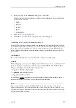
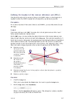
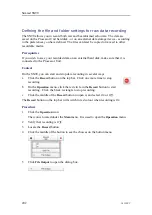
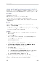
Defining the location of the motion reference unit (MRU)
The physical location of the motion reference unit (MRU) relative to the transducer is
required to allow the SN90 to adjust for roll and pitch as accurately as possible.
Prerequisites
For accurate location of the motion reference unit (MRU), you need the detailed vessel
drawings.
Context
The motion reference unit (MRU) measures the roll and pitch motions of the vessel.
Some sensor models also measure heave.
On the
MRU
page, you must define the physical location of the motion reference unit
related to the reference point you created on the
Ship
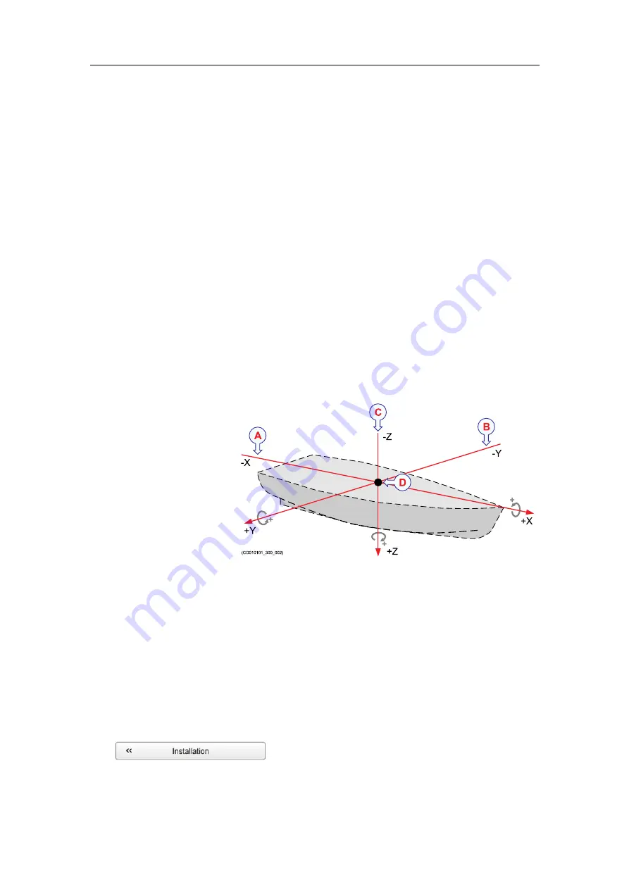
page. The rotation around the X, Y
and Z axis is used to compensate for misalignments made during the physical installation
of the motion reference unit. Such misalignments occur if the sensor is not placed in
parallel with the vessel’s horizontal and/or vertical planes. The required accuracy of the
offset and rotation angles depends on the accuracy requirement for the SN90 data.
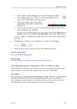
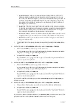
+Y
-Y
+Z
-Z
+X
-X
(CD010101_300_002)
A
B
C
D
+
+
+
A
Rotation around
the X-axis: In the
positive horizontal
direction (forward),
a positive rotation
is clockwise.
B
Rotation around
the Y-axis: In
the positive
horizontal direction
(starboard), a
positive rotation
is clockwise.
C
Rotation around the Z-axis: In the positive vertical direction (down), a positive
rotation is clockwise.
D
Reference point (origin)
Procedure
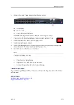
1
Click the
Setup
icon.
The icon is located under the
Main
menu. It is used to open the
Setup
menu.
2
On the
Setup
menu, click
Installation
.
Observe that the
Installation
dialog box opens. This dialog box contains a number
of pages selected by the menu on the left side.
Summary of Contents for Simrad SN90
Page 2: ......
Page 117: ...381298 C 115 Related topics Installation summary page 65 Installing the transducer ...
Page 236: ...234 381298 C 372915 Clamping frame Simrad SN90 ...
Page 295: ......
Page 296: ... 2016Kongsberg Maritime ISBN 978 82 8066 179 1 ...
Page 297: ......


