


550
442704/A
Details
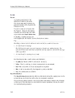
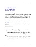
Boards
A graphic presentation of the
transceiver boards is provided.
The visual presentation reflects the
physical location of the boards in the
Transceiver Unit.
To select a transceiver board, click
the "button". The corresponding
transducer elements are identified.
Each button provides a small colour
coded indicator.
• No indicator: Status is OK. No actions are necessary.
• Yellow: This is a warning. A closer investigation is recommended.
• Red: This is an alarm. A closer investigation is required.
• Blue: A device monitored by the diagnostic system is disabled.
• Grey: No information is available.
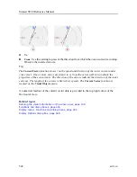
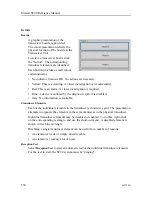
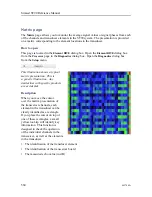
Transducer Elements
Each of the individual elements in the transducer is shown in a grid. The presentation
attempts to organize the elements in the same manner as in the physical transducer.
Individual transducer elements may be disabled or enabled. To do this, right-click
on the corresponding rectangle, and use the short-cut menu. A disabled element is
shown with a blue rectangle.
Disabling a single transducer element can be useful for a number of reasons.
• An element is weak or simply unserviceable.
• An element is creating a lot of noise.
Reception Test
Select
Reception Test
to start an automatic test of the individual transducer elements.
For the test to start, the ST90 system must be "pinging".
Simrad ST90 Reference Manual
Summary of Contents for Simrad ST90
Page 1: ...kongsberg com simrad Simrad ST90 REFERENCE MANUAL ...
Page 2: ......
Page 337: ...442704 A 335 Related topics Sonar views page 326 User interface ...
Page 413: ...442704 A 411 Related topics Menu system page 375 Display menu page 384 Menu system ...
Page 631: ...442704 A 629 Related topics Concept descriptions page 626 Concept descriptions ...
Page 687: ......
Page 688: ... 2021 Kongsberg Maritime ISBN 978 82 8066 211 8 ...
Page 689: ......
Page 690: ...Reference Manual Simrad ST90 ...


