20
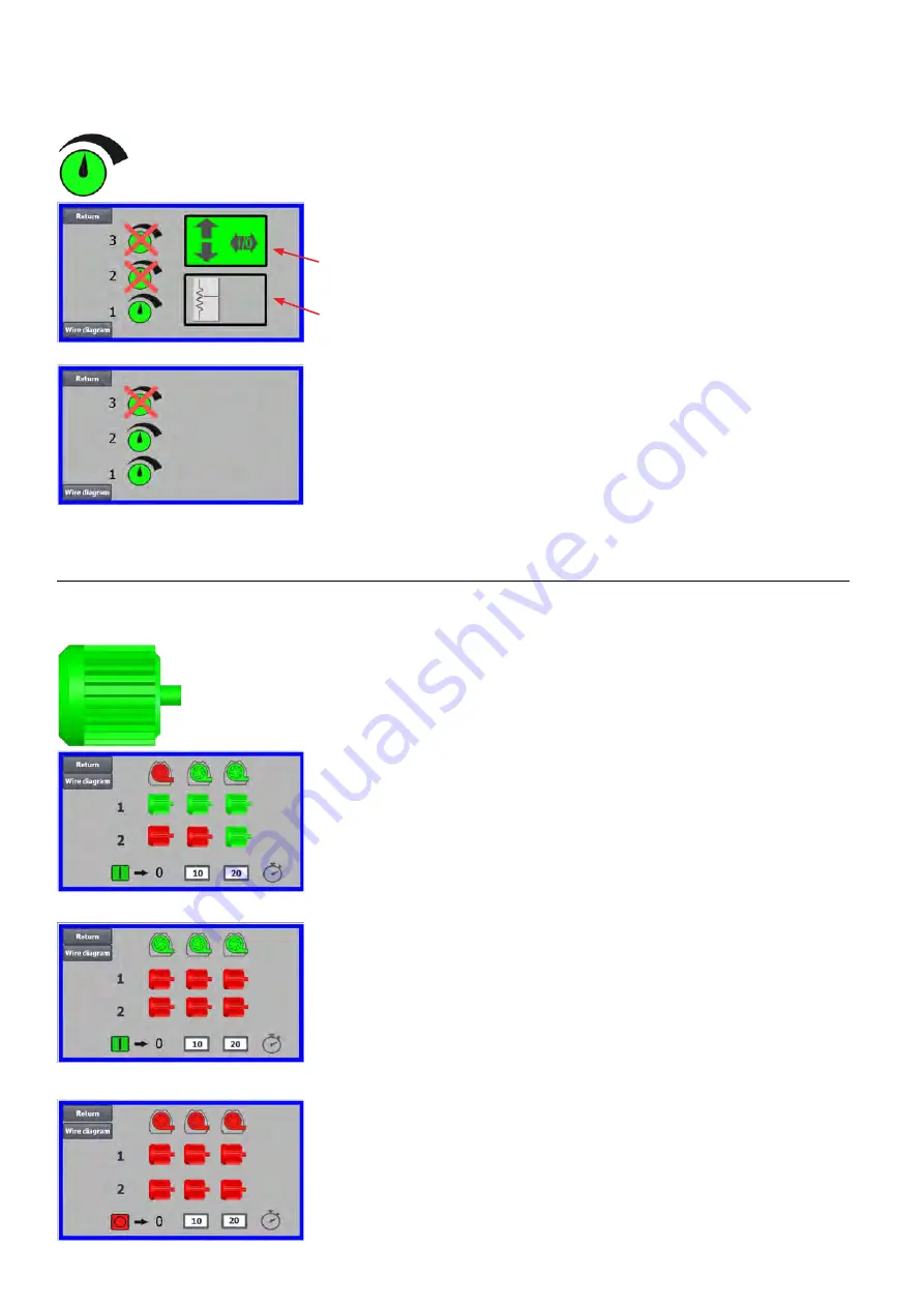
The icon gives access to setpoint setup
The screen on the left shows that only one setpoint has been selected,
since setpoints 2 and 3 are crossed over. The setpoint is adjusted from
either the up and down arrows on the operator panel, or via the digital inputs
on the PLC (shown in the box in the upper right corner). Incidentally, it is
seen that the setpoint of the blower is adjusted from the operator panel or
via the digital inputs on the PLC.
The setpoint can also be adjusted via the analog input on the PLC (shown
in the box in the lower right corner - the box will then switch to green back-
ground).
Pressing the Wire diagram shows a diagram showing the connection of the
digital inputs and outputs.
The screen on the left shows that 2 setpoints have been selected. The
setpoints are adjusted with the up and down arrows, and only on the op
-
erator panel. It is possible to choose between up to 3 different setpoints. If
you want to select more fixed setpoints, press the setpoint icons that are
crossed over, whereby the cross disappears.
If more than one fixed setpoint is selected, it is not possible to use the ana
-
log input to adjust the setpoints.
The icon gives access to the blower start and stop sequence
The blower control can start and stop up to 2 external electric motors, in
connection with starting and stopping the blower. It is possible to select the
order of both start / stop of blower / electric motors, and with which time
interval, the blower and each of the two electric motors must start or stop,
respectively.
The screen on the left shows an example where:
•
When the blower receives the start signal at time 0, the external electric
motor 1 is started (on a cutter, for example).
•
10 sec. after the start signal, the blower itself is started.
•
20 sec. after the start signal, the external electric motor 2 is started (on
a separator, for example).
Times 10 and 20 sec. are examples only.
The screen on the left shows the default settings for the start sequence.
There are no external electric motors connected to the blower, and the blow-
er starts when it receives the start signal.
When the menu for the blower's start sequence is left with the return but-
ton, you come to a corresponding stop sequence menu. The screen on the
left shows the default stop sequence. The stop sequence can be set in the
same way as the start sequence.
Pressing the icon Wire diagram, a diagram appears, showing the connec-
tion of the digital inputs and outputs.
S
t
a
r
t
s
e
q
S
t
a
r
t
s
e
q
S
t
o
p
s
e
q


