1 - 79
36 ADJUSTMENT
4.
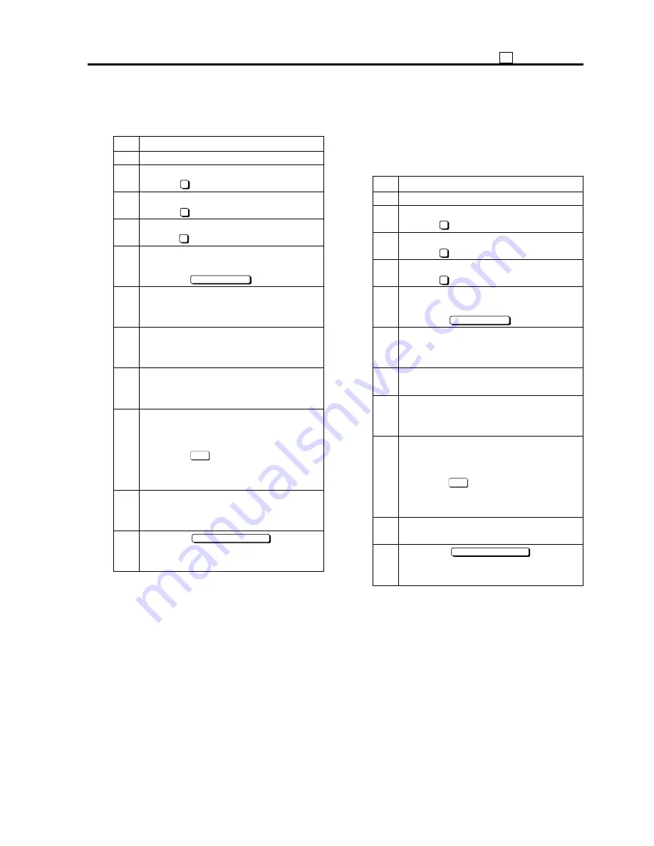
Printer lead edge timing adjustment
Adjusting the printer lead edge timing (Image
erasure amount).
Step
Operation
1
Enter the 36 mode.
2
[36 Mode Menu Screen]
Press “
2
Image adjustment.”
3
[Image adjustment mode menu Screen]
Press “
3
Timing adjustment.”
4
[Timing adjustment mode menu Screen]
Press “
4
Printer lead edge timing adj.”
5
[Printer lead edge timing adjustment
Screen]
Press the
COPY SCREEN
key.
6
Select A3-size paper, place pyramid
chart on original glass, and press the
Start button.
7
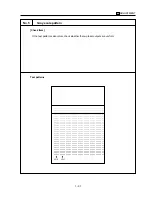
Check the printer leading edge blank cut
amount.
Specification: within 3 mm
8
If the printer leading edge blank cut
amount is not appropriate, press the C
button while pressing the P button.
9
[Printer lead edge timing adjustment
Screen]
Enter a value with the numeric keys and
Press the
SET
key.
Setting range: -20 to +40
1 step=0.1 mm
10
Repeat steps 5 to 10 until the printer
leading edge blank cut amount is within
specification.
11
Press the
PREVIOUS SCREEN
key to re-
turn to the Timing adjustment mode
menu Screen.
5.
Scanner restart timing adjustment
Adjusting the scanner restart timing during platen
copy.
Caution:
Printer restart timing adjustment must
be completed before performing this
adjustment.
Step
Operation
1
Enter the 36 mode.
2
[36 Mode Menu Screen]
Press “
2
Image adjustment.”
3
[Image adjustment mode menu Screen]
Press “
3
Timing adjustment.”
4
[Timing adjustment mode menu Screen]
Press “
5
Scanner restart timing.”
5
[Scanner restart timing adjustment
Screen]
Press the
COPY SCREEN
key.
6
Select A3-size paper, set a pyramid chart
on the original glass, and press the Start
button.
7
Check the tip timing.
Specification: within 3 mm
8
If the leading edge timing is not appro-
priate, press the C button while press-
ing the P button.
9
[Scanner Restart Timing Adjustment
Screen]
Enter a value with the numeric keys and
press the
SET
key.
Setting range: -60 to +20
1 step=0.1 mm
10
Repeat steps 5 to 10 until the leading
edge timing is within specification.
11
Press the
PREVIOUS SCREEN
key to re-
turn to the Timing adjustment mode
menu Screen.
Summary of Contents for 7075/FORCE 75
Page 1: ...FEBRUARY 2003 CSM 7075 F75 7085 F85 SERVICE MANUAL MODELS 7075 FORCE 75 7085 FORCE 85...
Page 2: ......
Page 3: ...7075 FORCE 75 7085 FORCE 85 SERVICE MANUAL FEBRUARY 2003...
Page 39: ...OUTLINE 1...
Page 40: ...Blank page...
Page 55: ...1 15 MAIN BODY 11 Paper Exit Drive Section FRONT Paper exit roller Paper exit motor M10...
Page 58: ...1 18 MAIN BODY 14 Web Drive Section FRONT Web drive motor M16 Cleaning web...
Page 59: ...UNIT EXPLANATION 2...
Page 60: ...Blank page...
Page 62: ...2 A 2 EXTERNAL SECTION Blank page...
Page 120: ...2 K 6 TRAY 3 PAPER FEED UNIT Blank page...
Page 126: ...2 L 6 BY PASS TRAY Blank page...
Page 130: ...2 M 4 VERTICAL PAPER CONVEYANCE SECTION Blank page...
Page 154: ...2 O 8 FIXING UNIT Blank page...
Page 165: ...DISASSEMBLY ASSEMBLY 3...
Page 216: ...3 H 4 TONER SUPPLY UNIT Blank page...
Page 224: ...3 I 8 CLEANING TONER RECYCLE UNIT Blank page...
Page 232: ...3 J 8 PAPER FEED UNITS OF TRAYS 1 AND 2 Blank page...
Page 240: ...3 K 8 TRAY 3 PAPER FEED UNIT Blank page...
Page 292: ...3 O 18 FIXING UNIT Blank page 3 O 16...
Page 293: ...MODELS 7075 FORCE 75 7085 FORCE 85 SERVICE SECTION FEBRUARY 2003...
Page 294: ......
Page 315: ...ADJUSTMENT 1...
Page 316: ......
Page 343: ...1 19 25 ADJUSTMENT Blank page 1 19 2...
Page 372: ...1 44 25 ADJUSTMENT 1 ADJUSTMENT Blank page...
Page 458: ...1 114 OTHER ADJUSTMENT Blank page 1 112 2...
Page 497: ...ISW 2...
Page 498: ......
Page 511: ...SERVICE 3...
Page 512: ......
Page 514: ...Blank page...
Page 550: ...3 18 SERVICE Blank page...
Page 551: ...ELECTRICAL PARTS LIST WIRING DIAGRAMS 4...
Page 552: ......
Page 611: ...JAM ERROR CODE LIST 5...
Page 612: ......
Page 625: ...5 13 JAM CODE LIST Blank page 5 11 2...
Page 659: ...TIMING CHARTS 6...
Page 660: ......
Page 678: ...6 18 TIMING CHARTS Blank page...
Page 679: ...INSTALLATION INSTRUCTIONS 7...
Page 680: ......
Page 692: ...Blank page...
Page 704: ...Blank page...
Page 724: ...Blank page...
Page 730: ...Blank page...
Page 736: ...Blank page...
Page 758: ...Blank page...
Page 780: ...Blank page...
Page 832: ...Blank page...
Page 833: ...APPENDIX 7085 OVERALL WIRING DIAGRAM...
Page 834: ......


