1 - 111
OTHER ADJUSTMENT
a.
Adjustment Method
Step
Operation
1
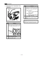
Raise the up/down plate.
2
Open the top cover.
3
Remove four screws (LT-401/411) or five
screws (LT-402/412) and detach the side
cover/right.
4
Open the JAM door and remove four
screws (LT-401/411) or six screws (LT-
402/412) to detach the front cover.
5
Remove the two screws (LT-401/411) or
three screws (LT-402/412) to detach the
clutch replacement cover.
Clutch replacement cover
Screws
6
Remove the five screws (LT-401/411) or
twelve screws (LT-402/412) to detach the
rear cover.
7
Loosen the two screws and adjust the
position of each paper up/down plate
drive pully using an adjustment screw so
that the front and rear of the oaoer up/
down plate are at the same height.
8
Secure the paper up/down plate drive
pulleys by tightening the two screws (per
up/down pulley) .
9
Install the rear cover, clutch replacement
cover, front cover, and side cover (right).
Screw
Rear cover
Screws
Screws
3
METHOD
REPLACEMENT
MODEL
7075/7085
MANUAL
SERVICE HANDBOOK
REVISED EDITION
3
DATE
Jan. 2002
PAGE
1-111
Screws
Side cover
(right)
Screws
Jam access door
Screws
Screws
Side cover (right)
Screws
(LT-402/412 only)
Screw
(LT-402/412 only)
Screw
(LT-402/412 only)
Screws
(Remove only the circled
screws for LT-401/411)
3
Summary of Contents for 7075/FORCE 75
Page 1: ...FEBRUARY 2003 CSM 7075 F75 7085 F85 SERVICE MANUAL MODELS 7075 FORCE 75 7085 FORCE 85...
Page 2: ......
Page 3: ...7075 FORCE 75 7085 FORCE 85 SERVICE MANUAL FEBRUARY 2003...
Page 39: ...OUTLINE 1...
Page 40: ...Blank page...
Page 55: ...1 15 MAIN BODY 11 Paper Exit Drive Section FRONT Paper exit roller Paper exit motor M10...
Page 58: ...1 18 MAIN BODY 14 Web Drive Section FRONT Web drive motor M16 Cleaning web...
Page 59: ...UNIT EXPLANATION 2...
Page 60: ...Blank page...
Page 62: ...2 A 2 EXTERNAL SECTION Blank page...
Page 120: ...2 K 6 TRAY 3 PAPER FEED UNIT Blank page...
Page 126: ...2 L 6 BY PASS TRAY Blank page...
Page 130: ...2 M 4 VERTICAL PAPER CONVEYANCE SECTION Blank page...
Page 154: ...2 O 8 FIXING UNIT Blank page...
Page 165: ...DISASSEMBLY ASSEMBLY 3...
Page 216: ...3 H 4 TONER SUPPLY UNIT Blank page...
Page 224: ...3 I 8 CLEANING TONER RECYCLE UNIT Blank page...
Page 232: ...3 J 8 PAPER FEED UNITS OF TRAYS 1 AND 2 Blank page...
Page 240: ...3 K 8 TRAY 3 PAPER FEED UNIT Blank page...
Page 292: ...3 O 18 FIXING UNIT Blank page 3 O 16...
Page 293: ...MODELS 7075 FORCE 75 7085 FORCE 85 SERVICE SECTION FEBRUARY 2003...
Page 294: ......
Page 315: ...ADJUSTMENT 1...
Page 316: ......
Page 343: ...1 19 25 ADJUSTMENT Blank page 1 19 2...
Page 372: ...1 44 25 ADJUSTMENT 1 ADJUSTMENT Blank page...
Page 458: ...1 114 OTHER ADJUSTMENT Blank page 1 112 2...
Page 497: ...ISW 2...
Page 498: ......
Page 511: ...SERVICE 3...
Page 512: ......
Page 514: ...Blank page...
Page 550: ...3 18 SERVICE Blank page...
Page 551: ...ELECTRICAL PARTS LIST WIRING DIAGRAMS 4...
Page 552: ......
Page 611: ...JAM ERROR CODE LIST 5...
Page 612: ......
Page 625: ...5 13 JAM CODE LIST Blank page 5 11 2...
Page 659: ...TIMING CHARTS 6...
Page 660: ......
Page 678: ...6 18 TIMING CHARTS Blank page...
Page 679: ...INSTALLATION INSTRUCTIONS 7...
Page 680: ......
Page 692: ...Blank page...
Page 704: ...Blank page...
Page 724: ...Blank page...
Page 730: ...Blank page...
Page 736: ...Blank page...
Page 758: ...Blank page...
Page 780: ...Blank page...
Page 832: ...Blank page...
Page 833: ...APPENDIX 7085 OVERALL WIRING DIAGRAM...
Page 834: ......


