background image

- 12 -

NI/IPL 3000361031 - 01

P

LANCHE

 4 / F

IGURE

 4

Summary of Contents for bizhub 43

Page 1: ...MULTIFUNCTION bizhub 43 TECHNICAL DOCUMENT 253 363 295 B KONICA MINOLTA...

Page 2: ...3000 359 745 02 2...

Page 3: ...NOTICE 3000 329 392 03 INSTALLATION GUIDE 3000 361 032 01 MAINTENANCE GUIDE 3000 329 394 03 ILLUSTRATED PART LIST 3000 361 031 01 PERSONNALISATION HFFV2 BIZHUB 43 3000 348 280 02 PRINTER TECHNICAL DOC...

Page 4: ...3000 359 746 02 4 DOCUMENT EVOLUTION Date Indice Action Author Requested by 20 09 10 A Initial creation C C A Cruchant 18 10 10 B Evolution C C A Cruchant...

Page 5: ...4 2 1 PHYSICAL CHARACTERISTICS 4 2 2 GENERAL TECHNICAL CHARACTERISTICS 4 3 FUNCTIONING 10 3 1 MAINBOARD 11 3 2 HFFV2 LCD PANEL TOP EQUIPPED SUB ASSEMBLY 21 3 3 HFFV2 KEYPAD SUB ASSEMBLY 24 3 3 1 Keypa...

Page 6: ...y 16 Touch screen 5 Paper stop 17 Access handle for the flatbed scanner 6 Finger print reader 18 Power cord connection 7 Numerical keypad 19 LINE 1 socket phone cord Connection 8 Master USB connector...

Page 7: ...window for bulky documents The control panel comprises a 7 inch colour graphic display equipped with a touch screen that allows users to view the command or alert messages and control the terminal a r...

Page 8: ...our Colour analysis Yes Resolution in dpi 600 Environment Operating The machine should not be exposed to direct sunlight Power supply 220 240 V 50 60 Hz 6 A Power consumption standby 25 W Power consum...

Page 9: ...adjustment Yes Margin adjustment left right Yes Duplex scan Yes Flatbed Scanner Type CCD Colour Colour analysis Yes Black White resolution in dpi 600 x 600 Colour resolution in dpi 600 x 600 Grey scal...

Page 10: ...bps V34 33 600 V90 capabilities No V90 increments No V34plus capabilities in bps 33 600 to 2 400 V34plus increments in bps 2 400 V32bis capabilities in bps 14 400 12 000 9 600 7 200 V32 capabilities i...

Page 11: ...broadcast performs No Remote broadcast reception report with reduced 1st page No Echo Protection Yes programmable Adding echo Protector Tone in V29 Yes programmable Rings number before answering Prog...

Page 12: ...rd and Screen Keyboard 64 QWERTY 62 or 64 keys Screen Colour graphics 7 lines of 20 characters 8 icons LED two colour green orange Address List Capacity 500 Type Name PSTN and SMS number E mail Transm...

Page 13: ...om multipages 6 16 15 16 s FB Scan Resolution HxV dpi 600x600 600x600 600x600 600x600 Output resolution HxV dpi 300x300 600x600 600x600 600x600 First copy time s 6 18 18 18 s Zoom 25 400 Automatic Dup...

Page 14: ...on the local area network Securised printer with data storage in hard disk Pictures pdf files printing from USB key Direct scan on USB key Remark s The machine does not have any facilities for managin...

Page 15: ...he executable code is stored in the flash memory Z1101 This flash memory is divided in two zones a zone reserved for the storage of the code and a zone reserved for the storage of the documents The co...

Page 16: ...system bus 8 bits data SPI Eeprom on holder SPI2 DDR2 SDRAM DDR2 SDRAM module SPI2 system bus Scanner IF GPIO Scanner IF Scanner IF RJ45 with transformer RJ11 CCFL PSU CCFL Power 18V 24V GPIO ELECTRO...

Page 17: ...13 DN 3000329392 03 Architecture module...

Page 18: ...ale Straight SATA connector SATA Power P4401 4 Male Straight ADF Motor sensor P5120 20 Male Straight FB Motor P5200 6 Male Straight CCD P5300 28 Male Straight Power supply P7103 5 Male Straight Power...

Page 19: ...eaker 2 HP O LF differential signal to loudspeaker Pin Signal name Input output Description 1 NC 2 R1F I O L1 local feedback 3 L1 I O PSTN signal 4 L2 I O PSTN signal 5 R2F I O L2 local feedback 6 NC...

Page 20: ...round 6 NC 7 RX I Differential pair received on network 8 RX I Differential pair received on network 9 VDDA33 LED Anode Power supply 10 ACTIVITY PHYAD2 ACTIVITY Yellow LED 11 LINK PHYAD1 LINK Green LE...

Page 21: ...power supply 3 VCC 5V power supply 4 GND Ground Pin Signal name Input output Description 1 ADF_OUT2A O ADF phase 2A motor drive 2 ADF_OUT1B O ADF phase 1B motor drive 3 ADF_OUT2B O ADF phase 2B motor...

Page 22: ...4 AGND Ground 5 P3V3 3 3V Power supply 6 VCC 5V Power supply 7 HOME I Home sensor input 8 RESET_CCD O Reset CCD module 9 SH_R O Sample Hold request 10 DGND Ground 11 DGND Ground 12 SPI_SDIO I O SPI se...

Page 23: ...used Pin Signal name Input output Description 1 P3V3 3V3 power supply 2 CS_MEZZ O Chip select 3 WR O Write enable 4 RD O Read enable 5 Reset_Mezz O Reset 6 IT_Mezz I Interruption 7 GND Ground 8 Data7...

Page 24: ...and 7 No connect 8 GND Ground 9 HFF_BD I Beam Detect 10 GND Ground 11 HFF_PPRDY I Printer Power Ready 12 HFF_RDY I Printer Ready 13 HFF_TOP I Top Page Detection 14 HFF_SBSY I Status Busy 15 HFF_STA I...

Page 25: ...nversion to drive an Analog 7 inch LCD panel Touch Screen function LCD panel inverter Finger print which is putted in a mezzanine The Front panel board integrates a PIC controller with integrated flas...

Page 26: ...e data input 4 GND Ground 5 Spi_do O SPI serial line data output 6 Spi_pic_cs I SPI serial line PIC select 7 Spi_clk I SPI serial line clock 8 Spi_fgpr O SPI serial line Finger print select 9 GND Grou...

Page 27: ...Input output Description 1 GND Ground for logic circuit 2 VCC 5V power supply 3 VGL O Negative power for scan driver 4 VGH O Positive power for scan driver 5 STVR O Vertical start pulse 6 STVL O Vert...

Page 28: ...ndependently The HFFV2 Keypad W FP Reader Equipped is done from The HFxv2 Keypad board The HFxv2 Keypad Mezzanine board One plastic cover and 2 light guides HFFv2 Keypad ASM One metal part 21 GND Grou...

Page 29: ...Straight Front panel P320 22 Female Right angled Pin Signal name Input output Description 1 GND Ground 2 GND Ground 3 NC 4 P3V3 3 3V power supply 5 P3V3 3 3V power supply 6 GND Ground 7 GND Ground 8 F...

Page 30: ...rint select 6 FS_INTR I Finger print interrupt 7 GND Ground 8 Key_L2 I Drive Keypad line 2 9 Key_L3 I Drive Keypad line 3 10 Key_C1 I Drive Keypad column 1 11 Key_C2 I Drive Keypad column 2 12 Key_C3...

Page 31: ...V power supply 5 P3V3 3 3V power supply 6 GND Ground 7 GND Ground 8 FS_SCS I Finger sensor serial line Chip select 9 FS_SCLK I Finger sensor serial line Clock 10 FS_MISO O Finger sensor serial line Da...

Page 32: ...V 0 9V Iout 2 5 A rend 81 Vout 1 25 V Iout 2 5A rend 80 1 5A 1A 1 1A mainboard P24VP 24V 0 45A P12VP 12V 70mA P5VC 5 1V 0 7A P3V35VP 3 35V 850mA P1V8P 1 8V 2A P1V25P 1 25V 2 3A 1 Vout 18 V Iout 800mA...

Page 33: ...l Time Clock 32 768kHz Y1100 32K768Hz 24 576MHz Y1301 12MHz Y4400 25MHz Y4100 24MHz Y4300 12MHz Y1200 Zoran 4230C MAX 6315 3 3V Vcc RESET HW_RESET MR SRT Flash RESET SOFT_RESET MODEM_RESET CCD_RESET S...

Page 34: ...he HFFv2 product is not powered ACTIVE mode The ACTIVE mode is characterized by the full HFFv2 MFP active with full function operational SLEEP mode The SLEEP mode is characterized by a full HFFv2 MFP...

Page 35: ...G PAPER 13 3 1 LOADING PAPER IN THE PAPER TRAY 13 3 2 LOADING PAPER LARGER THAN A4 SIZE IN THE PAPER TRAY 15 3 3 ADJUSTING THE ORIGINAL DOCUMENT OUTPUT TRAY 17 4 WALL CONNECTIONS 18 4 1 TELEPHONE AND...

Page 36: ...aneous 30 5 2 27Soft switch 27 Miscellaneous 30 5 2 28Soft switch 28 Miscellaneous 31 5 2 29Soft switch 29 Miscellaneous 31 5 2 30Soft switch 30 Miscellaneous 32 5 2 31Soft switch 31 Miscellaneous 32...

Page 37: ...nformation on the label on the back of your MFP Remark s The machine cannot be connected to an IT type power supply The mains input of the machine conforms to the overvoltage safety level 1 2 2 TELEPH...

Page 38: ...radiators or near air conditioning out lets see 2 1 of the Technical Description The room should be adequately ventilated Avoid locations where frequent vibrations occur Avoid locations where water o...

Page 39: ...of its carton Remove the protective side sections in the box Remove the plastic bag from the additional tray To install the additional tray see the installation guide of the additional tray 2 3 INSTAL...

Page 40: ...nnected to the connector of the terminal Tighten the screws at the both ends of the bottom of the duplex module Place the printer part in the final location in accordance with security directives see...

Page 41: ...assure the maximum copies per cartridge Hold the toner cartridge by its handle place it on a flat surface and pull the seal out horizontally Remark s Make sure you remove the toner cartridge cover hor...

Page 42: ...for a period of time defined by you Unpack the zen cube module Caution Do not allow the cartridge to come into contact with the mouth Avoid contact with eyes Wash your hands after manipulating the car...

Page 43: ...ing Firstly switch off the machine by pressing the On Off button position 0 and disconnect the mains cable Disconnect all cables connected to the machine If you are wearing an antistatic bracelet atta...

Page 44: ...IG 3000361032 01 10 2 6 2 INSTALLATION Unscrew the fast screw at the right back of the printer then slide the housing Uscrew the 12 screws cross head of the electronic cage Screw...

Page 45: ...Uscrew the 4 screws Torx N 10 of the rear plate Unconnect the flat cable from the mainboard and unscrew the 2 screws Torx N 10 of the second line modem Unconnect the 4 cables and uscrew the 3 screws...

Page 46: ...sconnect the 2 cables of the hard disk Data and power cable Unscrew the 4 screws Torx N 10 of the HDD support red arrows and remove it Remark s If the Second line modem was not installed remove 2 more...

Page 47: ...ve them 3 LOADING PAPER 3 1 LOADING PAPER IN THE PAPER TRAY The following section describes how to load paper into all trays of the multifonction Remark s If the paper size is higher than A4 see Loadi...

Page 48: ...the paper then smooth out the block of paper on a flat surface to avoid any paper jams or off centred printing Load the paper with the side to be printed facing up Check that the sheets do not exceed...

Page 49: ...o check define the size and type of paper that are loaded refer to the section Paper settings on the User guide 3 2 LOADING PAPER LARGER THAN A4 SIZE IN THE PAPER TRAY The following section describes...

Page 50: ...o the desired paper size Air the paper then smooth out the block of paper on a flat surface to avoid any paper jams or off centred printing Load the paper with the side to be printed facing up Check t...

Page 51: ...e the size and type of paper that are used on the terminal The terminal detect automaticaly the size of the standard paper To check define the size and type of paper that are loaded refer to the secti...

Page 52: ...ket on the wall Connect the end of the LAN cable not provided to your local network socket dedicated to your terminal 4 2 POWER LINE CONNECTION AND SWITCH ON Caution Refer to safety procedures in the...

Page 53: ...ters at delivery The access to these parameters is only authorized to maintenance and or installation technicians The MFP is equipped with a set of logic blocks referred to as SOS Soft Switches Each b...

Page 54: ...rth countries 5 0 SOS ATITEL Wait invitation to dial 0 Without wait invitation 1 With wait invitation 6 1 SOS IMPAUTO Automatic log print 0 No 1 Yes 7 00 Details on COM parameters in log reports JBIG...

Page 55: ...S ECHO Echo cancelling 0 No 1 Yes Bit Value Designation 1 1 SOS MODPRIV Communication in private mode 0 No 1 Yes 2 0 SOS DIS COURT Restricted DIS size 0 Long DIS complete 1 Short DIS 3 0 SOS TCF TCF a...

Page 56: ...trong level 7 1 8 0 Bit Value Designation 1 0 Reserved 2 0 Reserved 3 0 Reserved 4 1 SOS VEILMOD Sleep mode setting 0 Without 1 With 5 0 Reserved 6 0 Reserved 7 0 8 0 Reserved Bit Value Designation 1...

Page 57: ...TTENTION 0 Remote readout to Quadrige in transparent mode 1 Remote readout by fax 6 0 SOS ULTRETRO Fast deceleration of speed to works with servers which doesn t respect T30 rules 0 Without decelerati...

Page 58: ...ext e mail reception 0 No 1 Yes 2 1 SOS ACKNORECNET Send message not received reply on reception of corrupted messages 0 No 1 Yes 3 1 SOS EFFMSGNOK Delete corrupted messages 0 No 1 Yes 4 1 SOS PROMONE...

Page 59: ...No 1 Yes 7 0 Reserved 8 0 SOS T2CMPI Save Internet passwords on i2c card 0 No 1 Yes Bit Value Designation 1 0 SOS CMPHPPP PPP header compression address control field 0 No Compression 1 Compression 2...

Page 60: ...ted reception impossible 7 1 SOS LIGNE2 Existence of the second line used for dual line 0 No 1 Yes 8 0 SOS BRIDAGE LIGNE2 Activation of the second line used for dual ligne 0 Activation 1 No activation...

Page 61: ...6 0 7 0 SOS AFF_VIT_REELLE Show hide real communication rates 0 Show reduced rates 1 Show real rates 8 0 Reserved Bit Value Designation 1 0 Reserved 2 1 SOS PRINTIFCLOSE Starts printing documents rec...

Page 62: ...Optic sensor reconnaissance 0 No 1 Yes Bit Value Designation 1 1 SOS TRAITLIGERR T4 decoding line copying mode 0 For each line with an error 1 Only once then destroy 2 0 Reserved 3 0 Reserved 4 0 SOS...

Page 63: ...Enable status automatic transmission to the F x manager 0 No 1 Yes 8 0 SOS AUTO GDFTLR Enable remote readout automatic transmission to the F x manager Bit Value Designation 1 0 SOS JBIG SUPER G3 capab...

Page 64: ...card display PUT IN OTHER WAY sync chip detected 1 No dual chip card management display WRONG CARD if sync chip detected 4 0 Restriction on USB function 0 No 1 Yes 5 0 With or without duplication of...

Page 65: ...0 Without 1 With 8 0 Recall protection 0 Without 1 With Bit Value Designation 1 0 Reserved 2 0 Activation of the Notification menu 0 Enabled 1 Disabled 3 0 Activation of the validated menu 0 Enabled...

Page 66: ...erwriting of existing files in a directory for the ScanToDisk function 0 overwriting prohibited 1 overwriting authorised 8 1 Reserved Bit Value Designation 1 0 SOS COPLOC_INFINIE interne copy mode 0 n...

Page 67: ...ode 1 Test mode 6 0 SOS Zen Cube Enable 0 Disable functionning according to the User guide 1 Enable permanent activation 7 1 Intensity A limitation of line interface Values 0 deactivated or 1 Activate...

Page 68: ...communication in case of SUCCESS 0 Activated 1 Deactivated 2 0 Bip sound at the end of a FAX communication in case of ERROR 0 Activated 1 Deactivated 3 0 Cli displays the performance buffer for devel...

Page 69: ...case mail ftp smb key 0 PDF saved on MH format 1 PDF saved on MMR format 5 0 SMTP MIME mail encodage base 64 0 996 bytes per line high performance 1 76 byte per line rfc2045 6 0 SOS_SCANNER_PREHEAT_O...

Page 70: ...g PDF encapsulation 0 No conversion 1 Conversion 4 0 Reserved 5 0 Reserved 6 0 Reserved 7 0 Reserved 8 0 Reserved Bit Value Designation 1 0 Slope of U I curve Values 000 42 ohms 001 50 ohms 010 58 ohm...

Page 71: ...receive any incoming calls Make sure that all documents in the printer memory have been printed Disconnect the LAN cable Connect a PC using the USB cable Switch On the machine to PC download mode key...

Page 72: ...rom the DHCP Once is done on the PC start your web browser On the address field fill it with the address of the machine Press on Enter key of your keyboard The main web page appears Click on OK button...

Page 73: ...er Enter the service center number Emission Without Remote readout is not activated Fax Remote readout is activated Remote reading will be sent by fax File Remote readout is activate Remote reading wi...

Page 74: ...entered by the operator or generated by the software These parameters which are also present in the transmission report will be described further on Field Type Char Num Manual entry TVERS_TLR 0x00 cha...

Page 75: ...sion are the following T_INIT_FOUR 0x69 long No T_CPT_FOUR 0x6A long No T_SEUIL_FOUR 0x6B long Yes T_DATE_SEUIL_FOUR 0x6C char No T_DATE_CHG_FOUR 0x6D char No a Fields OPC are used for Feeder Roller S...

Page 76: ...XXXXX Third address XXXXXXXXXXXXXXXXXXXXXXXXXXXXXX Zip code XXXXXXXXXXXXXXX Town XXXXXXXXXXXXXXXXXXXXXXXXXXXXXX Country XXXXXXXXXXXXXXX Language XXXXXXXXXXXXXXX Phone number XXXXXXXXXXXXXXXXXXXXXXXXXX...

Page 77: ...TAL entered by the installer Town TVILLE entered by the installer Country TPAYS entered by the installer Language TLANGUE entered by the installer Phone number TTELEPHONE entered by the installer Prin...

Page 78: ...R trigger level expressed as the number of pages remaining to be printed for the transmission of a remote readout triggered by the revision threshold criterion entered by the installer Last remote ord...

Page 79: ...file Adress book Import export via Web site file format binary This operations are available on the Directory tab of the website On the left menu clic on Pc transfert item to access to the import exp...

Page 80: ...FF position 0 Disconnect the mains lead from the wall socket then disconnect all cables connected to the machine Close the paper stop of the scanner ouput tray Pack the terminal in its original plasti...

Page 81: ...HECKS SUPPLY VOLTAGES 6 1 5 ADMINISTRATOR FUNCTIONS AND SETTINGS 7 1 5 1 Administrator functions 7 1 5 2 Administrator settings 8 1 6 CPU BOARD REPLACEMENT 9 1 6 1 Procedure 9 1 6 2 Cabling specificat...

Page 82: ...394 03 1 11 4Procedure to use the makalu_210 software 15 2 DISASSEMBLY ASSEMBLY DESCRIPTION 20 2 1 LIST OF TOOLS 20 2 2 LIST OF WORKSHEETS 20 2 3 BLOCK DIAGRAM OF THE WORKSHEETS 21 3 HFFV2 CABLING SPE...

Page 83: ...tergents 1 1 1 PAPER TRANSPORT ROLLERS Set the on off switch to O off Open the ADF cover Clean the rollers and blades and the two blade guides on the mobile plate with a lint free cloth soaked with is...

Page 84: ...4 2 Cleaning the covers It is advisable to clean all covers during a maintenance visit 1 2 MAINTENANCE 1 2 1 PERIODICAL MAINTENANCE It is recommended to periodically perform the change of the followin...

Page 85: ...o calls you to retransmit his document Code 15 Incompatible coding Recipient machine does not match with the send document s encoding Code 19 Memory full Your fax can no longer receive incoming docume...

Page 86: ...n later Code 72 Internet disconnection The service has become temporarily unavailable try to connect again later 1 3 3 NETWORK CODES Code 80 Server Error Impossible to write the file The file could no...

Page 87: ...HTS Erase the users rights LOG Erase the logs COUNTERS ACTIVITIES Resets activity counter values ERRORS Resets errors list CONSUMABLES Set to 0 zero all consumable values Caution A new smart card will...

Page 88: ...M 0 20000 black toner threshold FUSER LIM 0 500000 fuser threshold SCANN PAD LIM 0 100000 feeder roller scanner threshold DEVICE NUMBER Part number of the machine SERIAL NUMBER Serial number of the ma...

Page 89: ...Format the HDD as described in the procedure see chapter 1 10 Caution It is vital that the EEPROM memory follows the printer as this memory contains the consumable counters the printer page counters...

Page 90: ...8 1 Select the menu Format Disk Select YES to confirm the formatting This operation could take approximately 20 minutes depending on HDD size When it s done check the encryption has been done correctl...

Page 91: ...s of Front panel board and keypad board 1 9 1 MATERIAL Material required is 1 x MPLAB ICD 2 module In circuit debugger Microchip tool 1 x USB device cable 1 x cable RJ11 P3 on the front panel board 1...

Page 92: ...s cable connect the ICD2 module to P3 connector 1 9 3 MPLAG CONFIGURATION Open executable file Click Configure Select Device Choose the PIC16F946 Click Programmer Select Programmer Choose MPLAB ICD2 M...

Page 93: ...from Reset Choose MPLAB ICD2 Close the debugger 1 10 REPLACING THE SCANNER Carry out the following procedure Carry out a remote readout if the function is enabled see chapter 6 in the Installation gu...

Page 94: ...allation documents SCT_U31_MAKALU_SP_627 Makalu HFC and HFF V2 printer and scanner drivers installation doc You can also install the drivers provided in CD Companion In this case refer to the installa...

Page 95: ...visible in the select box Caution The words True and False are sensitive to upper lower case Item Lang This section defines the language used at start up not to modify it manually write is made autom...

Page 96: ...he list of available scanners Click on Select The additional window closes Click on Enter Test Mode If the HFFV2 is connected by USB link and if it is ready the following screen appears Green color an...

Page 97: ...the scanner X is the horizontal adjustment length 297mm Y is the vertical adjustment width 210mm Step 2 If necessary you can change the Flat Bed scan setting Click on Flad Bed Scan Install a Test cha...

Page 98: ...the new values agree click Write to validate the proposed settings After writing the new values are sent to the scanner and the new values appears in the first column Step 3 If necessary you can chang...

Page 99: ...values agree click Write to validate the proposed settings After writing the new values are sent to the scanner and the new values appears in the first column When settings are finished click on Exit...

Page 100: ...T OF WORKSHEETS D1 Tray D2 Left front cover D3 Right front cover with keypad D4 Keypad assembly D5 Front panel assembly D6 USB front D7 PCB front panel D8 LCD screen D9 ADF scanner D10 Feeder roller m...

Page 101: ...Smartcard PCB Worksheet D15 Front panel PCB Worksheet D7 USB front Worksheet D6 LCD screen Worksheet D8 Flatbed scanner Worksheet D13 Loudspeaker Worksheet D21 Scanner tray Worksheet D24 Interface Wo...

Page 102: ...bed scanner cover Unstick the white panel located inside the flatbed scanner cover Clean the flap before to stick the new white panel Pull the tray outward lifting the back of the tray A to pass the s...

Page 103: ...sassembly Push from the bottom to the top at the bottom of the Left front cover in order to unclip it Slide the Left front cover Assembly Replace the different elements by performing the opposite acti...

Page 104: ...y Push from the bottom to the top at the bottom of the Right front cover in order to unclip it Slide the Right front cover Assembly Replace the different elements by performing the opposite action to...

Page 105: ...25 MG 3000329394 03 Tools Screwdriver torx N 7 Preliminary steps Worksheet D3 Disassembly Unscrew the 8 screws Rotate a little the Keypad assembly OBJECT KEYPAD ASSEMBLY D4...

Page 106: ...26 MG 3000329394 03 Unconnect the cable do not pull on wires Assembly Replace the different elements by performing the opposite action to that used to remove them OBJECT KEYPAD ASSEMBLY CONTINUED D4...

Page 107: ...crewdriver torx N 10 Screwdriver torx N 20 Preliminary steps Worksheet D2 to D4 Disassembly Unscrew the screw Torx N 10 for the ground plate picture Uscrew the 8 screws Torx N 10 of the front panel OB...

Page 108: ...front screws Torx N 20 of the scanner Unclip the bottom of the front panel assembly pull at the bottom of the noze Pull fron the bottom to the top on the front scanner to unclip the front panel OBJECT...

Page 109: ...little the front panel assembly and disconnect the 2 cables USB and front panel cables Assembly Replace the different elements by performing the opposite action to that used to remove them OBJECT FRON...

Page 110: ...ewdriver torx N 7 Preliminary steps Worksheet D5 Disassembly Unscrew the 2 screws Torx N 7 of the front USB Assembly Replace the different elements by performing the opposite action to that used to re...

Page 111: ...3000329394 03 Tools Screwdriver torx N 7 Preliminary steps Worksheet D5 Disassembly Disconnect the 2 flat cables and and the LCD back light Uscrew the 5 screws Torx N 7 of the PCB OBJECT FRONT PANEL...

Page 112: ...32 MG 3000329394 03 Remove the PCB like in the picture Assembly Replace the different elements by performing the opposite action to that used to remove them OBJECT FRONT PANEL PCB CONTINUED D7...

Page 113: ...33 MG 3000329394 03 Tools Screwdriver torx N 7 Preliminary steps Worksheet D7 Disassembly Remove the front panel keypad Remove the flat ferite do not dammage the flex OBJECT LCD SCREEN D8...

Page 114: ...ve the 4 ground spring Uscrew the 6 screws Torx N 7 of the LCD holder Remove the LCD screen Assembly Replace the different elements by performing the opposite action to that used to remove them OBJECT...

Page 115: ...Tools Flat screwdriver 2x6mm Preliminary steps None Disassembly Disconnect the ZenCube if this option is installed on the terminal To unclip the Interco trap insert the flat screwdriver in the slop O...

Page 116: ...36 MG 3000329394 03 Rotate the Interco trap to remove it Remark s Note the wire path of the ADF cable and the ground cable Disconnect the ground wire faston connector OBJECT ADF SCANNER CONTINUED D9...

Page 117: ...d as shown on the illustration below Apply manually a pressure at the base of both hinges use a flat screwdriver if necessary Remove the ADF scanner Assembly Replace the different elements by performi...

Page 118: ...B away from each other in the direction of the arrows shown on the illustration below and pull the cover backward at the same time Feeder roller module Pull on the lock in the direction of the arrow s...

Page 119: ...Remove the side cover Back door To unclip the back door insert the flat screwdriver in the slop Remove the back door Assembly Replace the feeder roller module performing the opposite action to that us...

Page 120: ...low Move the arms A and B away in the direction of the arrows Remove the input scanner assy Input paper assy Lift up the input paper assy as shown on the illustration below Move the arms A and B away...

Page 121: ...shoe assy by performing the opposite action to that used to remove it Replace the input paper assy by performing the opposite action to that used to remove it Replace the input scanner assy by perfor...

Page 122: ...le use the Phillips screwdriver for the ground cables Disconnect the motor cable Presence paper and cover closed sensors Remove the right ADF cover worksheet D10 Sensor are easily visible and can be r...

Page 123: ...Torx 10 Unscrew a little the tension holder to free the belt Replace the old Analysis roller belt by a new one Motor belt Remove the ADF module Remove the ADF cable from the wire holders D12 OBJECT AD...

Page 124: ...or frame assy and place the belt on the motor gear Fix the Tension motor frame assy on the gear frame with three Silent bloc Screws Unscrew a little bit the screw A Unscrew the screw B until the belt...

Page 125: ...motor Remove the two mounting screws of the motor Disconnect the motor cable if necessary Disassemble the motor with its cable Screws ADF feeder cover Motor mounting screws Motor cable D12 OBJECT ADF...

Page 126: ...cations if necessary Insert the short white frame plate edge B in its housing Insert the other edge A in its housing applying a downward pressure on the white frame plate Assembly Replace the ADF moto...

Page 127: ...ls Torx hex screwdriver Torx20 Preliminary steps Worksheet from D5 to D9 Disassembly Uscrew the 5 screws Torx N 20 of the upper scanner Unconnect the FB flat cable FB ground cable and the FB motor D13...

Page 128: ...e FB in printer cable Remove the FB scanner Pay attention to not pull on cables or on the FFC Assembly Replace the different elements by performing the opposite action to that used to remove them D13...

Page 129: ...ide the screw with a staple for example Remove the five mounting screws Remove the scanner upper assy Tension motor Remove both mounting screws Remove the scanner back door worksheet D10 CCD equipped...

Page 130: ...torx 10 screw Remove the two e ring which maintain the 2 gears Move out all gears Remove the CCD equipped with belt To re assembly motor assy on flat bed you have to place new grip ring by using grip...

Page 131: ...used to remove it and use new grip ring Replace the CCD motor by performing the opposite action to that used to remove it Replace the scanner upper assy by performing the opposite action to that used...

Page 132: ...ne Preliminary steps Worksheet D5 Disassembly Unclip the PCB Rotate the PCB then disconnet the cable Assembly Replace the different elements by performing the opposite action to that used to remove th...

Page 133: ...head Screwdriver torx N 10 Preliminary steps None Disassembly Unscrew the fast screw at the right back of the printer then slide the housing Uscrew the 12 screws cross head of the electronic cage D16...

Page 134: ...394 03 Uscrew the 4 screws Torx N 10 of the rear plate Assembly Replace the different elements by performing the opposite action to that used to remove them D16 OBJECT ACCESSIBILITY TO THE ELECTRONIC...

Page 135: ...steps Worksheet D16 Disassembly Unconnect the flat cable from the mainboard Uscrew the 2 screws Torx N 10 of the second line modem Assembly Replace the different elements by performing the opposite ac...

Page 136: ...N 10 Preliminary steps Worksheet D16 Disassembly Unconnect the 4 cables Uscrew the 3 screws Torx N 10 of the PCB Assembly Replace the different elements by performing the opposite action to that used...

Page 137: ...57 MG 3000329394 03 Tools Screwdriver torx N 10 Preliminary steps Worksheet D17 and D18 Disassembly Disconnect the 2 cables of the hard disk Data and power cable D19 OBJECT HARD DISK...

Page 138: ...0 of theHDD support red arrows Remark s If the Second line modem was not installed remove 2 more screws yellow arrows Assembly Replace the different elements by performing the opposite action to that...

Page 139: ...59 MG 3000329394 03 Tools Screwdriver torx N 10 Screwdriver 6 pans 5 5mm Preliminary steps Worksheet D19 Disassembly Disconnect all cables from the UC board D20 OBJECT CPU BOARD...

Page 140: ...with the screwdriver Torx N 10 yellow arrows and the 3 spacers with the Screwdriver 6 pans 5 5mm red arrows Assembly Replace the different elements by performing the opposite action to that used to re...

Page 141: ...9 and D13 Disassembly Unclip the loudpeaker by pushing on the clip Unconnect the loudspeaker cable from the UC then remove the loudspeaker Assembly Replace the different elements by performing the opp...

Page 142: ...driver torx N 10 Preliminary steps Worksheet D16 Disassembly Disconnect the LVPS cable from the DC DC card Remove the right side cover push on the 2 clips once the scannertray is in up position then r...

Page 143: ...out of the electronic cage Unscrew the 4 screws Torx N 10 of the LVPS holder Diconnect the harness Yellow arrow Assembly Replace the different elements by performing the opposite action to that used...

Page 144: ...64 MG 3000329394 03 Tools Screwdriver torx N 10 Preliminary steps None Disassembly Open the consummable trap Remove the top cover pull vertically on the top cover to unclip D23 OBJECT FRONT COVER...

Page 145: ...w the 2 screws Torx N 10 of the front cover Rotate the front cover to desengage the 2 hooks Assembly Replace the different elements by performing the opposite action to that used to remove them D23 OB...

Page 146: ...iver torx N 25 Preliminary steps Worsheets D20 D21 D22 and D23 Disassembly Remove the right side cover push on the 2 clips once the scannertray is in up position then rotate the cover Same operation f...

Page 147: ...nscrew the screw Torx N 10 of the Wifi trap and check is dongle are connected Remove dongle if necessary Unscrew the screw Torx N 25 of the Hinge Slide the hinge to remove it from the axis D24 OBJECT...

Page 148: ...03 Cut the 3 plastics link Note the position of all cables Remove the 3 front cables must pass trhough the scanner tray holde Remove the 2 rear USB boards unscrew the 4 screw torx N 7 D24 OBJECT SCANN...

Page 149: ...he position of all cables Remove the 2 USB boards must pass trhough the scannertray holde Remove the ground cable unscrew the screw torx N 10 Unconnect the FB in printer cable and the jack plug D24 OB...

Page 150: ...70 MG 3000329394 03 Note the position of all cables Remove the 2 cables must pass trhough the scannertray holde Rotate by 90 the scanner tray D24 OBJECT SCANNER TRAY CONTINUED...

Page 151: ...3000329394 03 Slide the scannertray to desengage it from the interface Assembly Replace the different elements by performing the opposite action to that used to remove them D24 OBJECT SCANNER TRAY CON...

Page 152: ...wdriver torx N 10 Screwdriver torx N 25 Preliminary steps Worsheets D20 D21 D21 D23 and D24 Disassembly Unscrew the screw Torx N 25 of the open button Unscrew the 2 screws at the back of the interface...

Page 153: ...rface to the printer Torx N 10 Assembly Replace the different elements by performing the opposite action to that used to remove them Remark s Refer to the paragraph HFFv2 cabling specification P 74 to...

Page 154: ...74 MG 3000329394 03 3 HFFV2 CABLING SPECIFICATION The specification describes the correct installation of the wires in the HFFv2 machine...

Page 155: ...RE 4 12 KEYPAD 13 PLANCHE 5 FIGURE 5 14 FRONT PANEL ASM 15 PLANCHE 6 FIGURE 6 16 FLATBED ASM 17 PLANCHE 7 FIGURE 7 18 OPEN BUTTON 19 PLANCHE 8 FIGURE 8 20 SCANNER TRAY ASM 21 PLANCHE 9 FIGURE 9 22 INT...

Page 156: ...PED 43 PLANCHE 20 FIGURE 20 44 ADF M H EQUIPPED 45 PLANCHE 21 FIGURE 21 46 ADF COVER M H ASSY 47 PLANCHE 22 FIGURE 22 48 INPURT PAPERWAY GUIDE EQUIPPED 49 PLANCHE 23 FIGURE 23 50 FLATBED SCANNER H M A...

Page 157: ...PLANCHE 31 FIGURE 31 66 PAPER EXIT 500 2 2 67 PLANCHE 32 FIGURE 32 68 FRAME DRIVE 69 PLANCHE 33 FIGURE 33 70 ELECTRICAL 71 PLANCHE 34 FIGURE 34 72 OPTION PAPER FEEDER 550 73 PLANCHE 35 FIGURE 35 74 D...

Page 158: ...4 NI IPL 3000361031 01...

Page 159: ...art REFERENCE column SAGEMCOM part number DESIGNATION column description of the item QTY column quantity R column repairability The letter R indicates that an item is repairable in the workshop 1 2 SP...

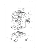
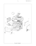
Page 160: ...6 NI IPL 3000361031 01 PLANCHE 1 FIGURE 1...

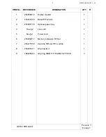
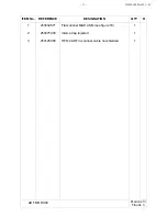
Page 161: ...53074778 Base HFFv2 asm 1 3 253087139 Optional paper tray 1 4 See 2 Line cord 1 5 See 2 Power cord 1 6 253232817 Memory extension HFXv2 1 7 253217550 Zencube Diffuser HFx sunline 1 8 253235371 Grip ri...

Page 162: ...8 NI IPL 3000361031 01 PLANCHE 2 FIGURE 2...

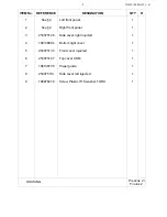
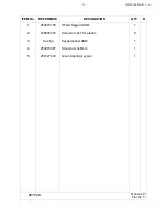
Page 163: ...Right front panel 1 3 253075126 Side cover right injected 1 4 186138694 Bottom right cover 1 5 253075134 Front cover injected 1 6 253075147 Top cover ASM 1 7 186138735 Paper guide 1 8 253075113 Side...

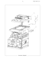
Page 164: ...10 NI IPL 3000361031 01 PLANCHE 3 FIGURE 3...

Page 165: ...361031 01 ITEM No REFERENCE DESIGNATION QTY R 1 253032671 Flat scanner M H ASM see figure 18 1 2 253075093 Interco trap injected 1 3 253125968 HFFv2 ADF in scanner cable not shielded 1 ADF MODULE PLAN...

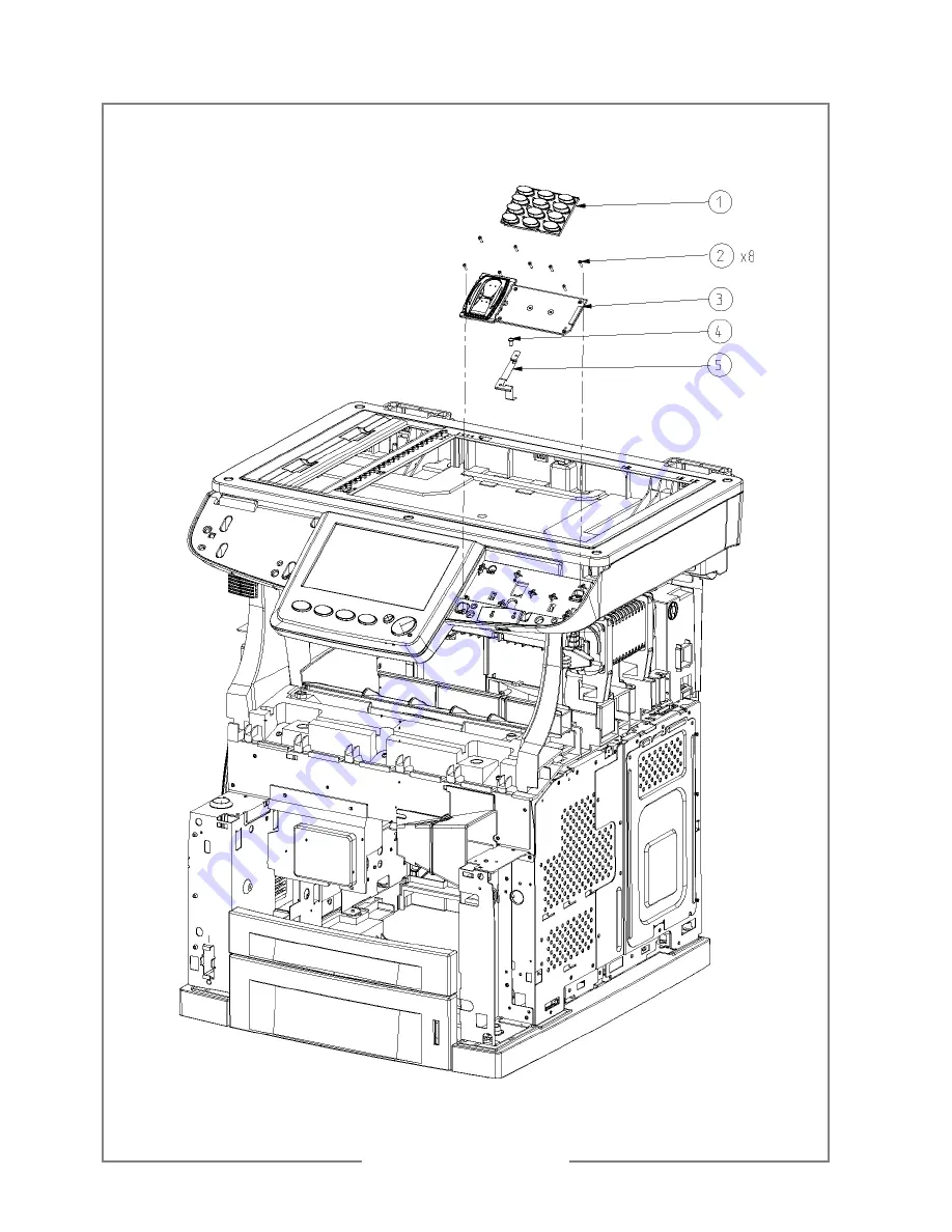
Page 166: ...12 NI IPL 3000361031 01 PLANCHE 4 FIGURE 4...

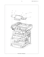
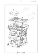
Page 167: ...TEM No REFERENCE DESIGNATION QTY R 1 253070155 HFxv2 Keypad ASM 1 2 189976372 Screw torx 2x7 for plastic 8 3 See 2 Keypad panel ASM 1 4 253074997 Screw torx 3x6mm 1 5 253127433 Ground spring keypad 1...

Page 168: ...14 NI IPL 3000361031 01 PLANCHE 5 FIGURE 5...

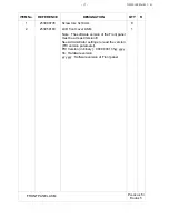
Page 169: ...83 LCD front cover ASM 1 Note The software version of the Front panel must be at least Version E See Administrator settings to read the version PIC version parameter PIC Version in binary 0000 0001 hh...

Page 170: ...16 NI IPL 3000361031 01 PLANCHE 6 FIGURE 6...

Page 171: ...01 ITEM No REFERENCE DESIGNATION QTY R 1 253090748 Screw torx 4 12mm 4 2 253033053 Flatbed scanner H M assy see figure 23 1 3 253096005 HFFv2 Flatbed ground cable 1 4 189955232 Flat cable 1 FLATBED A...

Page 172: ...18 NI IPL 3000361031 01 PLANCHE 7 FIGURE 7...

Page 173: ...L 3000361031 01 ITEM No REFERENCE DESIGNATION QTY R 1 253074864 Screw torx 6 12mm 2 2 253074851 Washer 6x12 2 3 253074822 Open button injected 1 4 253074843 Open button spring 1 OPEN BUTTON PLANCHE 7...

Page 174: ...20 NI IPL 3000361031 01 PLANCHE 8 FIGURE 8...

Page 175: ...1 ITEM No REFERENCE DESIGNATION QTY R 1 253074893 Scanner tray ASM 1 2 191031847 BLOC ALIM SECTEUR 100 240V 24V 2A SP 1 3 253074872 LVPS holder injected 2 4 253090735 Screw torx 3x10mm 4 SCANNER TRAY...

Page 176: ...22 NI IPL 3000361031 01 PLANCHE 9 FIGURE 9...

Page 177: ...23 NI IPL 3000361031 01 ITEM No REFERENCE DESIGNATION QTY R 1 253074819 Screw torx M3 8mm for metal 7 2 253074801 Interface injected 1 3 253123550 Screw torx M4 10 2 INTERFACE PLANCHE 9 FIGURE 9...

Page 178: ...24 NI IPL 3000361031 01 PLANCHE 10 FIGURE 10...

Page 179: ...REFERENCE DESIGNATION QTY R 1 253074799 HDD support ASM 1 2 189976351 Screw self tapping M3x5mm Torx 5 3 253169530 Mylar protection 1 4 253052798 ref card Mezz Modem 1 5 253074629 Mezz Modem cord 1 H...

Page 180: ...26 NI IPL 3000361031 01 PLANCHE 11 FIGURE 11...

Page 181: ...NI IPL 3000361031 01 ITEM No REFERENCE DESIGNATION QTY R 1 189976351 Screw self tapping M3x5mm Torx 2 2 253058120 UC spacer 3 3 See 2 Main PCB board programmed HFFV2 SAV 1 MAINBOARD PLANCHE 11 FIGURE...

Page 182: ...28 NI IPL 3000361031 01 PLANCHE 12 FIGURE 12...

Page 183: ...29 NI IPL 3000361031 01 ITEM No REFERENCE DESIGNATION QTY R 1 253058414 Rear plate 1 2 189976351 Screw self tapping M3x5mm Torx 4 3 253100768 Wire protection 1 BACK COVER PLANCHE 12 FIGURE 12...

Page 184: ...30 NI IPL 3000361031 01 PLANCHE 13 FIGURE 13...

Page 185: ...NI IPL 3000361031 01 ITEM No REFERENCE DESIGNATION QTY R 1 253114796 Trap holder Asm 1 2 253074819 Screw torx M3 8mm for metal 2 3 186138649 Trap 1 4 See 2 Printer HFFv2 1 TRAP HOLDER PLANCHE 13 FIGUR...

Page 186: ...32 NI IPL 3000361031 01 PLANCHE 14 FIGURE 14...

Page 187: ...253075085 Washer plastic 1 4 253088194 Washer D2D6 1 5 189976372 Screw torx 2x7 for plastic 2 6 189976108 Ferrite 1 7 186116833 Faston receiver PC2L25035LR KST 1 8 253108540 Ref Interco card 1 9 25307...

Page 188: ...34 NI IPL 3000361031 01 PLANCHE 15 FIGURE 15...

Page 189: ...tray 1 7 253074905 Scanner tray injected 1 8 253083029 HP HFF V2 1 9 253066891 Front panel cable 1 10 253074596 USB front cable 1 11 253066911 Cable Smartcart 1 12 253108579 Ref smartcard 1 13 2530749...

Page 190: ...36 NI IPL 3000361031 01 PLANCHE 16 FIGURE 16...

Page 191: ...R 1 253110384 Ref USB Board 1 2 186113907 Screw2x6mm washer6x0 5 torx 2 3 253097114 Light guide injected 1 4 189976372 Screw torx 2x7 for plastic 1 5 253058266 Keypad front panel HFF V2 1 6 253066903...

Page 192: ...38 NI IPL 3000361031 01 PLANCHE 17 FIGURE 17...

Page 193: ...253108582 Ref card DC DC 1 2 189976351 Screw self tapping M3x5mm Torx 7 3 253083040 DC DC 2 Wires Cables 1 4 253083032 DC DC 5 Wires Cables 1 5 253284019 DISQUE DUR 160GO HDD SATA 2 5 FORMATE 1 6 2530...

Page 194: ...40 NI IPL 3000361031 01 PLANCHE 18 FIGURE 18 1 2 3 4 5 6...

Page 195: ...ht cover colored 1 2 253033029 Input scanner assy 1 3 253032684 FLAP scanner H M equipped see figure 19 1 4 253063580 ADF MH equipped see figure 20 1 5 253029968 ADF left cover colored 1 6 253090748 S...

Page 196: ...42 NI IPL 3000361031 01 PLANCHE 19 FIGURE 19 1 2 3 4 5 6...

Page 197: ...R 1 253026582 Right hinge assembly 1 2 253090748 Screw plastic 4x12 torx 8 3 253026350 Left hinge assembly 1 4 253029294 Exit tray Makalu colored 1 5 253029252 Flap Makalu colored 1 6 253057107 Flap...

Page 198: ...44 NI IPL 3000361031 01 PLANCHE 20 FIGURE 20 1 2 3 4...

Page 199: ...E DESIGNATION QTY R 1 253032811 ADF cover M H assy see figure 21 1 2 253032788 Input paperway guide equipped see figure 22 1 3 253032725 ADF M H assembly 1 4 189978272 Photointerrupter optic GP1S73 SP...

Page 200: ...46 NI IPL 3000361031 01 PLANCHE 21 FIGURE 21 1 2 3 4 5 6 7 8 9 10 12 11 13 14 15 16 17 18 19 20 21 22...

Page 201: ...eeder stopper left colored 1 10 252990410 Counter roller 1 metal shaft 1 11 252990788 Spring 3 N 2 12 253090735 Screw plastic 3X10 torx 4 13 253029450 Counter roller colored 3 14 253029674 Feeder main...

Page 202: ...48 NI IPL 3000361031 01 PLANCHE 22 FIGURE 22 1 2 3 4 5 5 6 7 8...

Page 203: ...1 2 253029517 Counter roller 3 sup frame v 2 colored 2 3 253029538 Counter roller 3 sup colored 2 4 252989805 Counter roller shaft Makalu 2 5 252990770 Spring 1 5 N 4 6 253052032 Brush clip 4 7 253058...

Page 204: ...50 NI IPL 3000361031 01 PLANCHE 23 FIGURE 23 1 2 4 3 5 6...

Page 205: ...per cover flatbed Makalu assy 1 2 253033264 Screw cover colored 1 3 253005658 Screw torx 4x12 mm 5 4 253033040 Bottom cover flatbed Makalu assy 1 5 253056431 CCD BOX PRIMAX EQUIPED 1 6 253104927 FLATB...

Page 206: ...52 NI IPL 3000361031 01 1 5 6 2 3 4 J244 PLANCHE 24 FIGURE 24...

Page 207: ...N COVER KIT COVER OPEN SGM 1 2 186138652 HFFV2 PRN COVER COVER REAR 45PPM 1 3 186138694 HFFV2 PRN COVER COVER RIGHT J2 1 4 186138706 HFFV2 PRN COVER COVER LEFT J2 1 5 186138735 HFFV2 PRN COVER COVER S...

Page 208: ...54 NI IPL 3000361031 01 1 2 3 4 5 6 PLANCHE 25 FIGURE 25...

Page 209: ...ST 1 2 186138777 HFFV2 PRN CST 150 KIT ROLL ASSY RETARD 1 3 186138798 HFFV2 PRN CST 150 HANDLE EXTENSION 150 1 4 186138818 HFFV2 PRN CST 150 GUIDE END 150 1 5 186138821 HFFV2 PRN CST 150 150 PAPER CAS...

Page 210: ...56 NI IPL 3000361031 01 2 1 PLANCHE 26 FIGURE 26...

Page 211: ...57 NI IPL 3000361031 01 ITEM No REFERENCE DESIGNATION QTY R 1 186138850 HFFV2 PRN CST 550 550 PAPER CASSETTE 1 2 186138842 HFFV2 PRN CST 550 GUIDE END 550 1 PAPER CASSETTE 550 PLANCHE 26 FIGURE 26...

Page 212: ...58 NI IPL 3000361031 01 10 7 8 9 6 11 13 12 4 3 2 5 1 14 J220 J22 P220 J242 J243 P241 J241 J245 J240 P244 P243 P242 PLANCHE 27 FIGURE 27...

Page 213: ...EGI RUBBER J2 1 6 186138917 HFFV2 PRN FDR 150 CLUTCH ASSY PH 1 7 186139021 HFFV2 PRN FDR 150 KIT CHUTE REGI 45 1 8 186138938 HFFV2 PRN FDR 150 SENSOR REGI 1 9 186138946 HFFV2 PRN FDR 150 SPRING REGI 1...

Page 214: ...60 NI IPL 3000361031 01 3 1 2 4 J260 J248 J246 P247 J247 J26 PLANCHE 28 FIGURE 28...

Page 215: ...SIGNATION QTY R 1 186139034 HFFV2 PRN CST FDR GUIDE TRAY RIGHT 1 2 186139042 HFFV2 PRN CST FDR GUIDE TRAY LEFT 1 3 186139055 HFFV2 PRN CST FDR LOCK CST L 1 4 186139063 HFFV2 PRN CST FDR FEEDER2 ASSY 2...

Page 216: ...62 NI IPL 3000361031 01 14 8 9 13 12 11 5 6 2 1 15 3 10 4 17 16 7 3 J270 P131 P141 J140 J160 J170 J13 J14 J16 J17 J15 J31 J47 J45 J141 J46 J4647 J150 PLANCHE 29 FIGURE 29...

Page 217: ...7 186139167 HFFV2 PRN TNR ZONE COVER GUIDE CRU 1 8 See 2 HFFV2 PRN TNR ZONE HRNS ASSY FSR 1 9 186139191 HFFV2 PRN TNR ZONE LEVER FSR LH 34PPM 1 10 186139203 HFFV2 PRN TNR ZONE LEVER CRU FSR RH J2 1 1...

Page 218: ...64 NI IPL 3000361031 01 7 6 8 4 3 9 10 5 10 1 J29 J291 J290 J103 2 PLANCHE 30 FIGURE 30...

Page 219: ...ACTUATR FULL STACK 1 4 186139315 HFFV2 PRN PAP EXIT1 ROLL EXIT 1 5 186139328 HFFV2 PRN PAP EXIT1 MOTOR ASSY EXIT MT 1 6 186139336 HFFV2 PRN PAP EXIT1 GEAR 25 2 1 7 186139357 HFFV2 PRN PAP EXIT1 GEAR 2...

Page 220: ...66 NI IPL 3000361031 01 3 2 1 4 PLANCHE 31 FIGURE 31...

Page 221: ...ATION QTY R 1 186139422 HFFV2 PRN PAP EXIT2 ROLL PINCH FU 1 2 186143137 HFFV2 PRN PAP EXIT2 STOPPER FSR 4 3 186139435 HFFV2 PRN PAP EXIT2 COVER REAR 500 J2 1 4 186139443 HFFV2 PRN PAP EXIT2 KIT COV RE...

Page 222: ...68 NI IPL 3000361031 01 2 1 3 4 5 J43 J271 PLANCHE 32 FIGURE 32...

Page 223: ...186139456 HFFV2 PRN FRM DRV MAIN MOTOR J2 1 2 186139464 HFFV2 PRN FRM DRV GEAR ASSY HOUSING 1 3 186139477 HFFV2 PRN FRM DRV SPRING RELEASE 1 4 186139485 HFFV2 PRN FRM DRV GEAR 9 1 5 186139498 HFFV2 P...

Page 224: ...70 NI IPL 3000361031 01 7 2 3 8 4 5 6 9 1 J44 J48 J480 J20 J30 J22 J10 J11 J27 J18 J400 P270 PD2750A P271 J1821A J102 J40 J41 J42 J24 P2083 P3070 P221 P248 P245 PLANCHE 33 FIGURE 33...

Page 225: ...9539 HFFV2 PRN ELEC SWITCH ASSY EXIT J2 1 4 See 2 HFFV2 PRN ELEC HRNS ASSY AC SGM 1 5 186139571 HFFV2 PRN ELEC FFC ASSY ESS 1 6 186139592 HFFV2 PRN ELEC HARNESS ASSY CHUTE 1 7 See 2 HFFV2 PRN ELEC HVP...

Page 226: ...72 NI IPL 3000361031 01 1 2 3 4 5 5 6 7 8 JD2083 J83 J80 P855 P820 J820 J81 J84 J801 P802 J802 J800 PD8483 J810 P801 J82 J85 9 PLANCHE 34 FIGURE 34...

Page 227: ...V2 OPT FDR 550 HRNS ASSY SIZE FDR1 1 4 186139646 HFFV2 OPT FDR 550 FRAME CVR L A4 MAT 1 5 186139654 HFFV2 OPT FDR 550 FOOT 1 6 186139667 HFFV2 OPT FDR 550 FRAME CVR R550 J2 1 7 186139675 HFFV2 OPT FDR...

Page 228: ...74 NI IPL 3000361031 01 3 3 2 2 2 3 3 4 9 5 6 8 9 7 3 2 2 3 2 9 9 25 24 10 10 10 11 12 13 14 15 16 18 20 19 21 22 23 17 1 JD2750 J50 J51 J52 J53 J54 J530 J520 PLANCHE 35 FIGURE 35...

Page 229: ...LER 1 11 186139802 HFFV2 OPT DPLX GEAR IDLE 29 1 12 186139815 HFFV2 OPT DPLX GEAR IDLE 47 34PPM 1 13 186139823 HFFV2 OPT DPLX GEAR IDLE 77 34PPM 1 14 186139836 HFFV2 OPT DPLX GEAR IDLE 57 37 1 14 1861...

Page 230: ...NI IPL 3000361031 01 76...

Page 231: ...is changed 253336243 1 4 Telephone line cord 189721446 1 5 AC power cord 189641841 2 1 Left front panel 253107030 2 2 Right panel with finger print 253075051 4 3 Keypad panel ASM 253058162 13 4 Printe...

Page 232: ...PERSO 3000 348 280 02 2...

Reviews: