background image

1-21

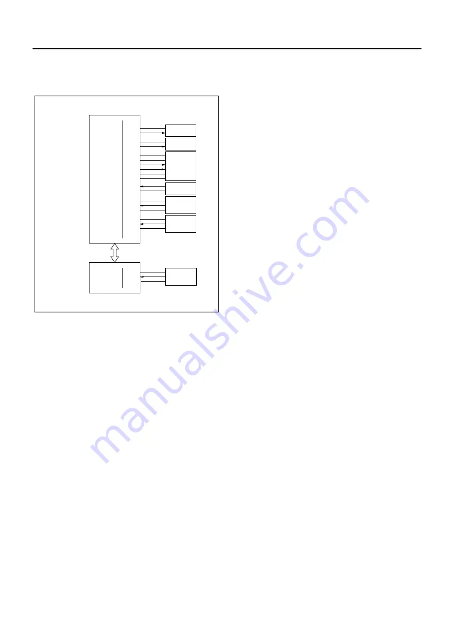
ADU NIP ROLLER DRIVE SECTION

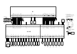
[4] ADU Control

SD101

205-A1
205-A2

204-1
204-2

206-B1
206-B2
206-B3
206-B4
206-A9
206-B5

203-5
203-6

205-A3
205-A7
205-A10

205-A4
205-A8
205-A11

24V DC

SD101 DRIVE

24V DC

SD102 DRIVE

24V DC

PGND1

ADU-S/S
ADU-F/R

SGND1

5V DC1

PS1010

SGND1

5V DC1

PS106

SGND1

5V DC1

PS107

SGND1

ADUDB

SD102

M101

103-3
103-4
103-5

5V DC1

PS101

SGND

CB

PS1010S

PS106

PS107

PS101

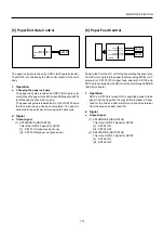
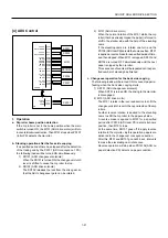
1. Operation

a. Nip roller home position detection

If the nip roller is not in the home position when the main
switch is turned ON, the M101 (ADU drive motor) will turn
in counterclockwise direction. Then M101 stops when PS107
(roller PS) detects the nip roller.

b.  Stacking operation after the face side copying

If a specified period of time has elapsed after the detection
of the trailing end by the PS101 (ADU conveyance 1 PS),
the following loads will be turned ON simultaneously:

1) SD101 (ADU changeover solenoid)

When the SD101 is turned ON, the changeover clutch
lever is shifted to cause the nip roller to stop.

2) SD102 (ADU drive solenoid)

The SD102 releases the lock from the drive gear so
that the ADU changeover gate can be rotated.

3) M101 (ADU drive motor)

When the normal rotation of the M101 starts, the nip
roller (that has already nipped the paper) is forced to
shift to the stacker side with the help of the elevating
cams.
If the elevating cams are rotated one turn and the
PS106 (ADU cam PS) detects the home position, M101
is applied a reverse brake for a specified period of time,
and then stopped. When M101 is stopped, SD101 and
SD102 are turned OFF simultaneously until the next
paper is nipped by the nip roller.
This sequence of events will be repeated until a speci-
fied number of stacking has finished.

c.  Changeover operation for the back side copying

The following loads will be turned ON to conduct paper re-
feeding when the back side copying starts.

1)  SD101 (ADU changeover solenoid)

When SD101 is turned ON, the driving to the nip roller
is disengaged.

2)  M101 (ADU drive motor)

The M101 rotates in the reverse direction to shift the
changeover/clutch lever to the opposite side of the nip
rollers.
Another reverse rotation is applied to the elevating
cams to shift the nip roller to the paper exit side.
A reverse brake is applied to M101 for a specified
period after PS106 (ADU cam PS) detects its home
position, then M101 stops.
At the same time, SD101 goes off to apply reverse
rotation to the nip roller. By this operation, papers are
delivered to the changeover conveyance section.
After this, M101 and SD101 go on at 2.6 sec. intervals
to make the elevatating cam rotate once.
Reverse operation will stop when PS1010s (ADU no
paper detection PS) detects no paper condition.

Summary of Contents for Copier 2223

Page 1: ...eed Control 1 13 ADU NIP ROLLER DRIVE SECTION 1 14 1 Construction 1 14 2 Mechanism 1 14 3 Disassembly and Reassembly 1 16 4 ADU Control 1 21 LCT PFU SECTION 1 23 1 Construction 1 23 2 Mechanism 1 23 3 Disassembly and Reassembly 1 24 4 LCT Lift Control 1 28 2 DIAGRAMS DB 307 107 607 ELECTRICAL PARTS LAYOUT DRAWING 2 1 DB 307 107 607 CONNECTOR LAYOUT DRAWING 2 3 DB 307 107 607 OVERALL WIRING DIAGRAM...

Page 2: ... 90 g m2 fine quality paper ADU capacity 10 sheets max 80g m2 Tray capacity LCT 1000 sheets max 80g m2 PFU 250 sheets max 80g m2 3 Particulars of Machine Power requirements DC24V 5V supplied from the main body Max power consumption 50 VA Weight Approx 36 kg Machine dimensions 4 Maintenance Maintenance Same as the main unit Service life Same as the main unit 5 Operating Environment Temperature 10 C...

Page 3: ...ain body to main body ADU section ADU stacker section Changeover conveyance section LCT paper feed roller Conveyance rollers Upper LCT tray PFU paper feed roller PFU tray Conveyance rollers Middle Conveyance rollers Lower DB 307 CENTER CROSS SECTION ...

Page 4: ...ller 1 Drive gear of main body ADU Conveyance Drive Drive gear of main body LCT PFU Conveyance Drive Conveyance roller Lower PFU paper feed roller Conveyance roller Middle Conveyance roller Upper LCT paper feed roller Changeover conveyance roller 3 Changeover conveyance roller 2 1 Main Drive 2 ADU Nip Roller Drive DRIVE SYSTEM SECTION DB 307 DRIVE SYSTEM SECTION ...

Page 5: ...gear drive Paper route change Paper exit change gate ADU changeover roller drive Gear driven by Main motor gear drive 1 Paper route change The route of a paper from the fuser section is changed by the paper exit change cover gate one path is to cause the paper to come out of the exit and the other is to cause the paper to go to the ADU reversal section In case of one sided copying mode paper goes ...

Page 6: ...red to the exit tray ADU stack section ADU nip rollers Changeover conveyance section MAIN DRIVE SECTION 3 Disassembly and Assembly Caution Disconnectthepowercableplugfromthewall outlet 1 Removing reinstalling the ADU Conveyance Unit Lower a Procedure 1 Open the upper main body 2 Remove the four set screws then remove the exit tray with the mounting plate CAUTION If the sorter is already installed ...

Page 7: ... Lower 6 Reinstall the guide in the reverse order of removal but the following should be carefully executed Note 1 MakesuretheholesintheADUgatesolenoid SD103 are aligned with the two locating pins Pins holes ADU gate solenoid SD103 ADU Conveyance Unit Lower Holes Pins 2 Align the two pins on the back of the ADU Convey ance unit Lower with the holes in the main body MAIN DRIVE SECTION ...

Page 8: ...s Exit tray Exit tray mounting plate 3 Remove the four set screws then remove the ADU guide unit Set screws ADU guide unit 4 Remove the main body tray two set screws and the lower main body cover left Set screws Lower main body cover left 5 Remove the set screw and the left rear cover sliding it to downward to clear the protruding part 6 Remove the two set screws then remove the ADU conveyance gui...

Page 9: ... conveyance guide Upper Set screws Outside 9 Disconnect the relay connector CN118 for the ADU conveyance 1 PS PS101 then remove the ADU con veyance guide Upper 10 Reinstall the ADU conveyance guide upper in the reverse order of removal 3 Removing reinstalling the ADU changeover con veyance guides 1 to 4 a Procedure 1 Remove the main body from the DB 307 2 Open the ADU left door 3 Remove the two se...

Page 10: ...CN236 form the ADU paper feed PS PS103 and the bundle of wires from the bundle tie 7 Remove the set screw and one plain washer then remove the changeover conveyance guide 1 Set screw Changeover conveyance guide 1 Plain washer ADU paper feed PS PS103 Connector CN236 Set screws Changeover conveyance guide 2 8 Remove the four set screws then remove the change over conveyance guide 2 9 Remove the four...

Page 11: ... conveyance guide 3 Changeover conveyance guide 3 Plain washer Fulcrum screw MAIN DRIVE SECTION ADU paper conveyance 2 PS PS104 ADU paper conveyance 3 PS PS105 Connector CN231 Connector CN232 Set screws Changeover conveyance guide 4 12 Remove the two set screws then remove the change over conveyance guide 4 13 Disconnect the connectors CN231 CN232 from ADU paper conveyance PS2 and 3 PSs PS104 PS10...

Page 12: ... E ring and bushing from the shaft of the LCT paper feed roller LCT paper feed roller shaft E ring Bushing MAIN DRIVE SECTION 5 Remove the E ring and bushing from the front side of the LCT paper feed roller shaft ten take the LCT paper feed roller unit out LCT paper feed roller shaft E ring Bushing 6 Remove each E ring then remove the paper feed roller and pin from the roller shaft Pin Roller shaf...

Page 13: ...ay 3 Remove the PFU tray 4 Remove the spring then remove the drive gear by removing the lock of the bushing Drive gear Lock of bushing Spring 5 Remove the lock of the bushing then remove the bushing and roller shaft 6 Remove the lock and the paper feed roller from each of the shaft Lock Roller shaft Paper feed roller 7 Reinstall the roller in the reverse order of removal ...

Page 14: ...N paper exit gate up H SD103 OFF paper exit gate down 6 Paper Feed Control SD104 217 1 217 2 215 A1 215 A2 24V DC SD104 DRIVE 24V DC SD105 DRIVE ADU DB SD105 CB Paper is fed from the LCT or PFU by transmitting the drive force from M1 main motor to the paper feed roller using SD104 LCT solenoid or SD105 PFU paper feed solenoid SD104 and SD105arecontrolledbytheCB controlboard throughADUDB ADU drive ...

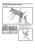
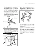
Page 15: ...oller elevating CAM Hexagon cut at roller shaft end Mechanism Paper conveyance Paper changeover Nip roller drive Nip roller rotation control Nip roller elevating Nip roller dragging preven tion 2 Mechanism 1 Stacking operation when copying first side The nip roller is rotated by the main motor M1 of the main body through the train of gears The first paper passes the ADU changeover gate end and is ...

Page 16: ...r direc tion by the movement of the changeover clutch lever The paper is fed into the changeover conveyance section along the changeover gate The ADU changeover solenoid SD101 is turned ON and the gears are disengaged to stop the rotation of the nip roller At the same time the ADU drive motor M101 is ON for 2 6 seconds to return the nip roller one pitch to the home position side by means of the ni...

Page 17: ...agging prevention The hexagonal end of the nip roller prevents dragging of the nip roller from the once behind Hexagonal end Nip roller 3 Disassembly and Reassembly Caution Disconnectthepowercableplugfromthewall outlet 1 Removing reinstalling the gear bracket a Procedure 1 Remove the DB rear cover 2 Remove the three set screws then remove the DB left side cover I Set screws DB Left side cover 3 Re...

Page 18: ...1 Turn the nip roller elevating cam so that the detecting plate of the ADU cam PS PS106 faces the direction as shown in the figure below 2 Position the changeover clutch lever shift arms are in the position as shown in the figure below then rein stall the gear bracket Bushing E ring Bushing E ring Bushing Pin E ring E ring Gear 6 Remove the spring and four set screws Set screws Set screws Spring S...

Page 19: ...ews then remove the stack guide plate Stack guide plate Set screws 4 Cut the three harness bands 5 Disconnect the connectors CN230 CN205 from the ADU no paper detecting PS PS1010S and ADU paper HP PS PS109 and remove the stack guide plate from the top of this machine ADU paper HP PS PS109 Harness bands Connector CN205 ADU no paper detecting PS PS1010S Connector CN230 6 Reinstall the guide plate in...

Page 20: ...at the home position side to the stack side by turning the ADU drive motor M101 by hand then remove them through the nip roller round hole 16th nip roller Wire Spring 4 Reinstall the nip rollers in the reverse order of removal and pay attention to the following Note When installing arrange them as shown in the figure below Nip roller 1st 16th Traling end Leading end ADU drive motor M101 Round hole...

Page 21: ...ip roller elevating cam back ADU front door Set screws 4 Remove the three set screws then remove the gear cover Set screws Gear cover 5 Remove the four set screws then remove the nip roller elevating cam front Set screws Nip roller elevating cam front ADU cam PS PS106 Set screws Nip roller elevating cam back Connector CN224 8 Reinstall the cams in the reverse order of removal Note 1 Adjustniprolle...

Page 22: ...ed the paper is forced to shift to the stacker side with the help of the elevating cams If the elevating cams are rotated one turn and the PS106 ADUcamPS detectsthehomeposition M101 is applied a reverse brake for a specified period of time and then stopped When M101 is stopped SD101 and SD102 are turned OFF simultaneously until the next paper is nipped by the nip roller This sequence of events wil...

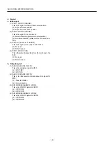
Page 23: ...10s ADUDB This is the signal for no paper in the stacker L No paper H Detects paper 4 PS101 PS101 CB Thisisthesignalforpaperfeedfromthemainbodytothe ADU L No paper H Detects paper b Output signal 1 ADU S S ADUDB M101 This is the start stop signal to M101 L M101 OFF H M101 ON 2 ADU F R ADUDB M101 This is the clockwise counterclockwise drive signal for M101 L Reverse rotation H Normal ratation 3 SD1...

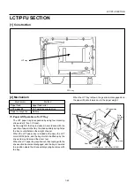
Page 24: ...uxiliary spring helps the tray counterbalance the weight of paper When the LCT paper tray is loaded with paper the LCT motor M102 turns and the tray starts to be lifted up by the drive wire wound around the driver reel When the LCT paper tray is pulled out the coupling with the drive section becomes disengaged and the tray is lowered to a position where the drive auxiliary spring becomes with the ...

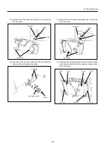
Page 25: ...oves up and down smoothly by pressing it by hand 2 After replacing the wires adjust the paper tray inclina tion a Procedure 1 Pull the LCT tray out toward the front then remove it out of the fixation rail 2 Remove the four set screws then remove the LCT tray front cover 3 Disconnect the auxiliary wire from the drive auxiliary spring Tray front cover Set screws Auxiliary wire Drive auxiliary spring...

Page 26: ...t by removing the E ring and drive pulley E ring Drive pulley front Front wires 7 Remove the two E rings and pulleys then remove the two front wires E ring Pulley Front wire Front wires 8 Pass two new wires through the holes in the front of the paper tray and install the two pulleys and secure them with the E rings E ring E ring Pulley Front wire Pulley Front wire Paper tray ...

Page 27: ...e rear of the paper tray install the two pulleys and secure them with the E rings E rings Pulley Pulley Rear wire Rear wire Paper tray 11 Insert the ends of a new auxiliary wire and the rear wires into the holes in the drive shaft install the drive pulley and secure it with the E ring E ring Drive pully Rear Rear wires Auxiliary wire 12 Turn the rear drive shaft one turn counterclockwise from the ...

Page 28: ...ve auxiliary spring through the pulley Drive pulley Rear Auxiliary wire 4turns Auxiliary wire Drive auxiliary spring Pulley 15 Loosen the set screw and adjust inclination of the paper tray by moving the adjuster then tighten the set screw Set screw Adjuster 16 Reinstall the tray front cover with the four set screws 17 Reinstall the LCT tray ...

Page 29: ...LCT lifting after paper feeding is conducted When the top of the paper lowers due to paper feeding from the LCT tray PS110 is turned OFF and M102 drives the paper lift plate up When PS110 LCT upper limit PS detects the top of the paper M102 stops 2 Signal a Input signal 1 PS114 PS114 ADUDB This is the LCT tray insertion detection signal L LCT tray insertion detected H LCT tray not detected 2 PS110...

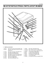
Page 30: ... PS DB 307 607 19 SSB110 PFU paper size detection board DB 307 607 1 MS101 ADU front door inter lock switch DB 307 107 2 MS102 ADU lower conveyance door inter lock switch DB 307 107 3 PS101 ADU paper conveyance 1 PS DB 307 107 4 PS102 ADU paper exit PS DB 307 107 5 PS103 ADU paper feed PS DB 307 107 6 PS104 ADU papaer conveyance 2 PS DB 307 107 7 PS105 ADU paper conveyance 3 PS DB 307 107 8 PS106 ...

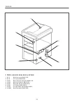
Page 31: ...B 307 107 2 M102 LCT motor DB 307 607 3 SD101 ADU changeover solenoid DB 307 107 4 SD102 ADU drive solenoid DB 307 107 5 SD103 ADU gate solenoid DB 307 107 6 SD104 LCT solenoid DB 307 607 7 SD105 LCT paper feed solenoid DB 307 607 8 ADUDB ADU drive board DB 307 607 5 4 6 7 2 1 3 8 ...

Page 32: ...AGRAMS 117 111 118 85 86 224 227 236 230 235 229 224 222 225 226 223 221 228 220 254 251 250 252 253 256 238 255 257 232 231 233 259 200 210 203 216 219 205 204 215 214 DB307 107 607 CONNECTOR LAYOUT DRAWING ...

Page 33: ... 100 1 100 2 100 8 100 9 101 A1 101 A2 101 A3 101 B3 101 B4 101 B5 101 B6 101 A6 101 A7 101 A8 101 A4 101 A5 101 A9 101 B1 101 B2 100 3 100 4 100 5 100 6 100 7 101 B7 101 B8 101 B9 24VDC 5VDC SGND0 PGND1 OP_SCAN1 CASSCAN4 CASSCAN5 KEYRET3 KEYRET2 KEYRET1 KEYRET0 PS121 PS122 PS123 PS110 LCT_HP LCT_NOB PS114 OP_SD1 OP_SD2 PS123 LCT_S S LCT_F R OPADD_V OPADD_L1 OPADD_L0 5VDC1 PS105 SGND1 5VDC1 PS106 ...

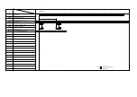
Page 34: ... PS101 ADU Cam PS PS106 ADU Changeover Solenoid SD101 ADU Drive Solenoid SD102 ADU Drive Motor M101 ADU No Paper Delection PS PS1010 Symbol Time sec Item COPY ON 0 1 2 3 4 5 6 7 8 9 10 11 12 13 M101 Normal Normal rotation Deceleration 0 9 s 0 9 s 0 9 s 1 2 s 0 9 s 0 9 s 0 9 s 1 2 s ...

Page 35: ...veyance 1 PS PS101 ADU Cam PS PS106 ADU Changeover Solenoid SD101 ADU Drive Solenoid SD102 ADU Drive Motor M101 ADU No Paper Detection PS PS1010 Symbol Time sec Item COPY ON 0 1 2 3 4 5 6 7 8 9 10 11 12 13 M101 Normal Reverse rotation Deceleration 2 6 s ...

Page 36: ...s 300ms 1725ms 1770ms 1770ms 4700ms 1900ms 2000ms 1200ms 2000ms 1200ms 1900ms 2000ms 2000ms Symbol Item Time sec Main motor Optics Drive Optics F R Exposure Lamp Bias Charge Elimination LED PCL Charge Transfer Separation Upper Paper Feed SD Regist SD Upper Paper Feed PS Rre shutter Sensor Exit Detecting Sensor Optics Home Position Sensor Optics Brake Sensor Charge erasure in non image area ...

Reviews: