Field Service Ver. 1.0 Jun. 2008
5. Service Mode
DF-612/SP-503/MS-501
Adjustment / Setting
9.
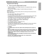
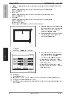
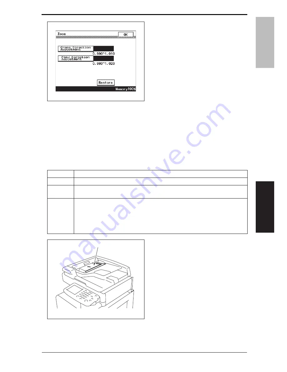
Touch [Cross Direction Adjustment]
or [Feed Direction Adjustment].
• Cross Direction Adjustment: A (Main
scan direction)
• Feed Direction Adjustment: B (Sub
scan direction)
10.
Press the Clear key, and then enter
the numeric value from the 10-Key
Pad.
• If the line is longer than the specifica-
tions, adjust toward the reduction side.
• If the line is shorter than the specifica-
tions, adjust toward the enlargement
side.
11.
Touch [OK].
12.
Press the Reset key.
13.
Repeat steps 3 to 12 until the reference line lengths comply with the specifications.
14.
Touch [OK] on the Service Mode screen.
15.
Turn OFF the main power switch, then wait for 10 sec. or more and turn ON the main
power switch.
5.2.2
Feed
1.
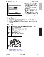
Load the test chart [1] in the ADF.
2.
Call the Service Mode to the screen.
See P.146 of the main body service manual.
3.
Touch [Machine Adjustment]
o
[Scan Area]
o
[Test Copy].
A0EYF3E510DA
Functions
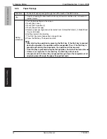
• To adjust the scan start positions in the main and sub scan directions of the ADF.
Use
• Use upon setting up the ADF.
Adjustment
specification
• Width A (Leading edge misalignment): 0 ± 2.0 mm
• Width B (Lateral edge misalignment): 0 ± 2.0 mm
Adjustment
range
[Leading Edge]: -4.0 to +4.0
[Centering]: -72 to +72 (x 0.04 mm)
[Leading (2nd)]: -5.0 to +5.0
[Centering (2nd)]: -72 to +72 (x 0.04 mm)
[Leading (3rd)]: -6.0 to +6.0
[Centering (3rd)]: -72 to +72 (x 0.04 mm)
A0EYF3C500DA
[1]
Y109850-7 Service Manual 35


