Ch.2 Unpacking and Installation
< 68 >
DRYPRO Vstage MODEL 793 Installation Manual Ver.1.00 2004.11
8
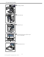
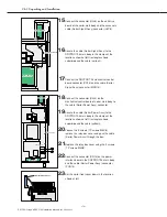
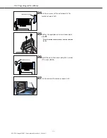
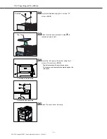
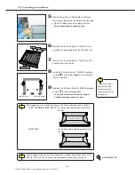
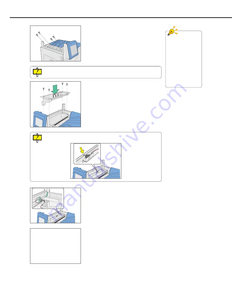
Pass the 2 separation unit cables (connector
nos. JP165, JP166) from the hole in the HPRO
discharge unit through to the rear side.
7
Secure the separation unit using 4 screws (TP
screws M4X6).
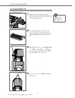
- The separation unit should be lowered carefully
ensuring that the embossed markings on the heat-
processing discharge unit mesh with the
positioning holes.
Be careful that the passing sensor and actuator on the separation unit do not
become separated from the unit.
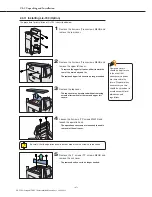
6
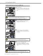
Remove the 4 screws (TP screws M3X6) and
remove the heat-processing discharge unit
guide.
- The removed heat-processing discharge unit cover
is no longer needed.
Be careful not to drop removed screws inside the main body.
9
Secure the 2 cables to the main body at 2
locations using the clamps shown at left.
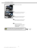
Components no
needed should be kept
for use in the event that
unnecessary options
are removed in the
future. Disposal of any
unnecessary covers
should be carried out in
accordance with local
ordinances and
regulations.


