FS-107
2-10
1
OUTLINE
2
UNIT EXPLANA
TION
3
DIS./ASSEMBL
Y
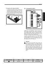
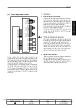
2.
Signals
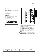
a.
Input signals
(1) PS709 (PS709
→
FS CB)
Detection signal of the home position of the
alignment plate (rear)
[L]: Non-home position
[H]: Home position
(2) PS710 (PS710
→
FS CB)
Detection signal of the home position of the
alignment plate (front)
[L]: Non-home position
[H]: Home position
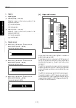
b.
Output signals
(1) M702 OUT A, M702 OUT A
–
, M702 OUT B,
M702 OUT B
–
(FS CB
→
M702)
Drive control signal for M702
(2) M703 OUT A, M703 OUT A
–
, M703 OUT B,
M703 OUT B
–
(FS CB
→
M703)
Drive control signal for M703
(3) M704 OUT A, M704 OUT A
–
, M704 OUT B,
M704 OUT B
–
(FS CB
→
M704)
Drive control signal for M704
[4]
Paper exit control
PS3
5VDC
PS3
SGND
PS702
5VDC
PS702
SGND
PS703
5VDC
PS703
SGND
PS707
5VDC
PS707
SGND
PS701
5VDC
PS701
SGND
FS CB
M702
24VDC
24VDC
M702 OUT A
M702 OUT A
M702 OUT B
M702 OUT B
24VDC
24VDC
24VDC
5VDC
5VDC
SGND
SGND
PGND
PGND
PGND
SGND
SGND
M ACK
SGND
S REQ
M RXD
SGND
S ACK
M REQ
SGND
M TXD
MAIN BODY
M708
M708 DRIVE 1
M708 DRIVE 2
M707
M707 DRIVE 1
M707 DRIVE 2
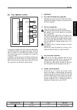
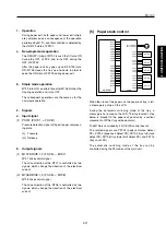
Papers that have already been aligned or stapled are
exited by the paper exit roller.
A mechanical clutch is connected to M702 (paper exit
motor). A mechanical clutch can convey the forward
direction driving power to the exit roller with certain
movement.
The M702 is responsible for speed control for connection
with the mechanical clutch, for sending the alignment
section at the reversal rotation, and also during the usual
paper exit.
The M702 is controlled by the FS CB (FS control board).
The related signals are M707 (paper pressure motor),
M708 (stapler motor), PS701 (paper pressure PS), PS702
(paper entrance detect PS), PS703 (paper exit detect PS),
and PS707 (no paper detect PS).
0V
24V
0V
24V
0V
24V
Summary of Contents for FS-107
Page 2: ...CN26NF1780 KONICA CORPORATION COPYRIGHT 2001...
Page 4: ...Blank page 2 1 OUTLINE 2 UNIT EXPLANATION 3 DIS ASSEMBLY...
Page 5: ...1 OUTLINE 2 UNIT EXPLANATION 3 DIS ASSEMBLY OUTLINE 1...
Page 6: ...Blank page 2 1 OUTLINE 2 UNIT EXPLANATION 3 DIS ASSEMBLY...
Page 14: ...Blank page 2 1 OUTLINE 2 UNIT EXPLANATION 3 DIS ASSEMBLY...
Page 15: ...1 1 OUTLINE 2 UNIT EXPLANATION 3 DIS ASSEMBLY UNIT EXPLANATION 2...
Page 16: ...Blank page 2 1 OUTLINE 2 UNIT EXPLANATION 3 DIS ASSEMBLY...
Page 32: ...Blank page 2 1 OUTLINE 2 UNIT EXPLANATION 3 DIS ASSEMBLY...
Page 33: ...1 OUTLINE 2 UNIT EXPLANATION 3 DIS ASSEMBLY DISASSEMBLY ASSEMBLY 3...

