FS-107
3-2
1
O
UTLINE
2
UNIT EXPLANA
TION
3
D
IS./ASSEMBL
Y
(4)
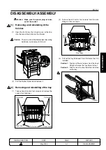
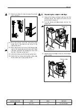
Install by reversing the removal procedure.
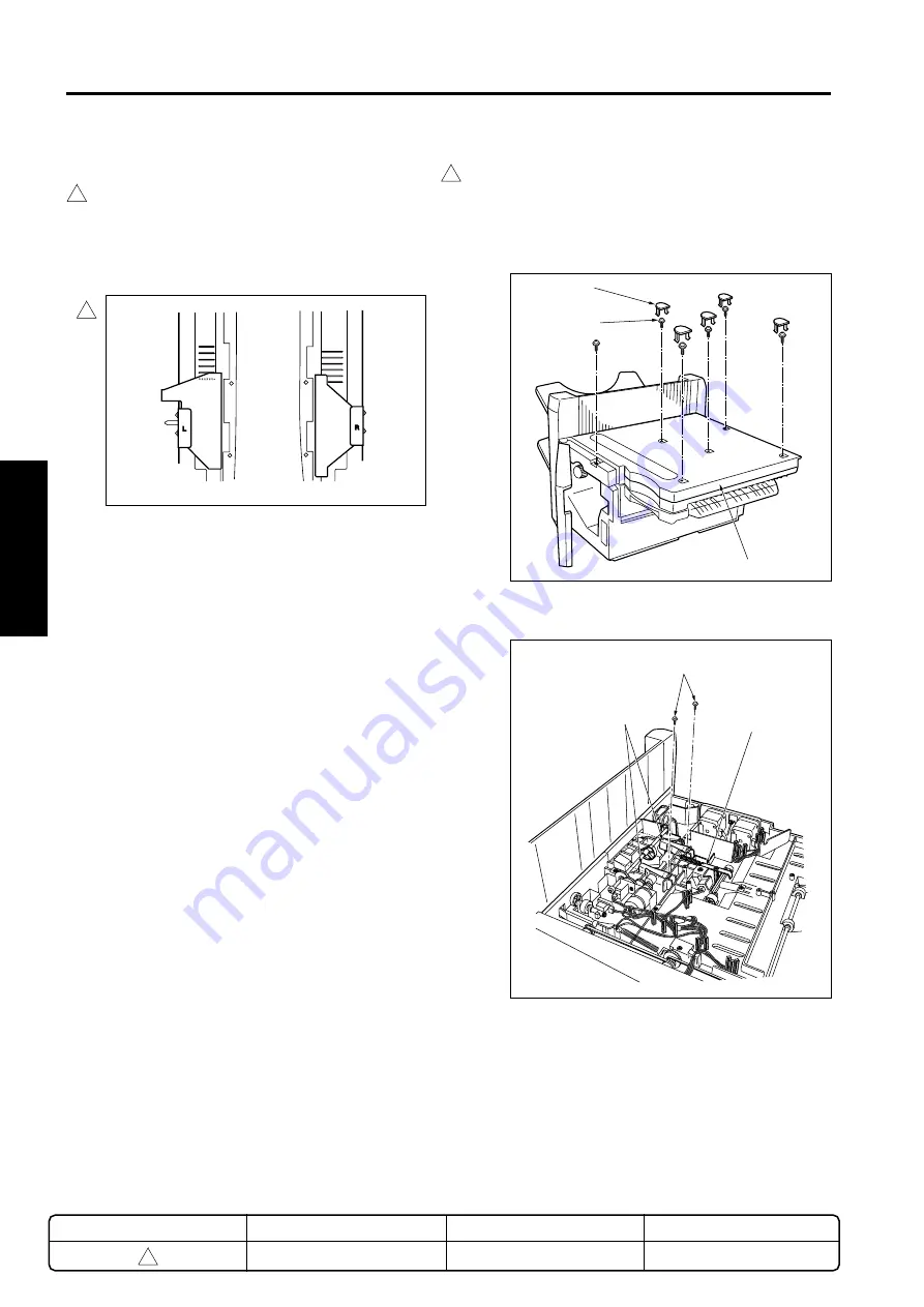
Caution:
In case of fixing the tray frame to the fixed
fittings, make sure the set screws are fas-
tened so that the tray is horizontal.(Use
the 6 marks at each of the front and rear as
guides for horizontal adjustment.)
Set screws
Lids
Paper conveyance cover
Set screws
Plate spring rollers
[3] Replacing the paper exit roller/A
(1)
Remove the finisher from the main body.
(2)
Take off 5 lids and 6 set screws and remove the
paper conveyance cover.
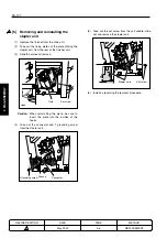
(3)
Take out each of the single springs and set screws
and remove the plate spring roller.
Caution:
Do not remove the screws for the spring
adjustment plate.
Spring
adjustment
plate
METHOD
REPLACEMENT
PAGE
3-2
DATE
May 2000
REVISED EDITION
1
1
1
1
Rear
Front
Summary of Contents for FS-107
Page 2: ...CN26NF1780 KONICA CORPORATION COPYRIGHT 2001...
Page 4: ...Blank page 2 1 OUTLINE 2 UNIT EXPLANATION 3 DIS ASSEMBLY...
Page 5: ...1 OUTLINE 2 UNIT EXPLANATION 3 DIS ASSEMBLY OUTLINE 1...
Page 6: ...Blank page 2 1 OUTLINE 2 UNIT EXPLANATION 3 DIS ASSEMBLY...
Page 14: ...Blank page 2 1 OUTLINE 2 UNIT EXPLANATION 3 DIS ASSEMBLY...
Page 15: ...1 1 OUTLINE 2 UNIT EXPLANATION 3 DIS ASSEMBLY UNIT EXPLANATION 2...
Page 16: ...Blank page 2 1 OUTLINE 2 UNIT EXPLANATION 3 DIS ASSEMBLY...
Page 32: ...Blank page 2 1 OUTLINE 2 UNIT EXPLANATION 3 DIS ASSEMBLY...
Page 33: ...1 OUTLINE 2 UNIT EXPLANATION 3 DIS ASSEMBLY DISASSEMBLY ASSEMBLY 3...


