background image

FS-601 Field Service Ver2.0 Sep. 2004

Trouble code

4-13

IV


T

rou

b

lsh

oot

in

g

2.3.5

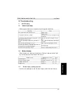
C0B3A:Rear Aligning Plate Motor malfunctions

A. Detection timing

B. Action

Malfunction code

Description

C0B3A

The Rear Aligning Plate Home Position Sensor (PI5-FN) is not unblocked even 
after the lapse of a given period of time after the Rear Aligning Plate has started 
moving from its home position to a position out of the home position.

The Rear Aligning Plate Home Position Sensor (PI5-FN) is not blocked even after 
the lapse of a given period of time after the Rear Aligning Plate has started moving 
from a position out of the home position to the home position.

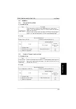
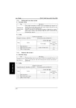
Relevant electrical parts

Rear Aligning Plate Home Position Sensor (PI5-
FN)
Rear Aligning Motor (M5-FN)

Finisher Control Board (PWB-A FN)

Step

Action

WIRING DIAGRAM

Control signal

Location

(Electrical compo-

nents)

1

Check the motor and sensor connectors 
for proper connection, and correct as 
necessary.

-

-

2

Check the connector of motor for proper 
drive coupling, and correct as neces-
sary.

-

-

3

PI5-FN I/O, sensor check

PWB-A FN CN5 FN-15

E-8

4

M5-FN operation check when the Power 
Switch is turned OFF and ON.

-

B-7

5

PWB-A FN replacement

-

E-6

Summary of Contents for FS-601

Page 1: ...SERVICE MANUAL 2004 09 Ver 2 0 FS 601 THEORY OF OPERATION ...

Page 2: ......

Page 3: ... has been made To indicate clearly a section revised show in the lower outside section of the correspond ing page A number within represents the number of times the revision has been made NOTE Revision marks shown in a page are restricted only to the latest ones with the old ones deleted When a page revised in Ver 2 0 has been changed in Ver 3 0 The revision marks for Ver 3 0 only are shown with t...

Page 4: ......

Page 5: ...on 2 1 2 Drive system 2 2 3 Paper path 2 3 4 Mechanical operations 2 4 4 1 Horizontal transport mechanism 2 4 4 1 1 Paper path switching mechanism 2 4 4 1 2 Finisher paper transport mechanism 2 5 4 2 Finishing tray mechanism 2 6 4 2 1 Non sort mode 2 6 4 2 2 Sort mode 2 7 4 2 3 Staple Mode 2 7 4 2 4 Center staple booklet mode 2 8 4 2 5 Paper stacking with finishing tray 2 9 4 2 6 Aligning mechanis...

Page 6: ...position Operation 4 3 5 Stapling unit moving control 2 17 4 3 6 Elevator tray mechanism 2 18 4 4 Booklet tray 2 19 4 4 1 Overall composition 2 19 4 4 2 Transport operation in saddle section 2 20 4 4 3 Folding mechanism 2 24 4 4 4 Paper folding start position 2 25 ...

Page 7: ...s to be Stapled Plain Paper A6R to A3 Wide 5 1 2 8 1 2R 5 1 2 8 1 2 to 12 1 4 18 60 to 256 g m2 16 to 68 lb 60 to 90 g m2 16 to 24 lb Elevator Tray No of Sheets Height A4R 8 1 2 11R or smaller 1000 150 mm B4 8 1 2 14 or larger 500 75 mm Envelop OHP Film Label Paper Thick Paper Max Min Controlled by whichever reached earlier CD311 15 mm 86 mm 20 sheets FD457 2 mm 139 7 mm Paper Type Paper Size Weig...

Page 8: ...tor Tray A4R 8 1 2 11R or smaller 2 to 50 B4 8 1 2 14 or larger 2 to 25 Controlled by whichever reached earlier Paper Type Paper Size Weight Tray Capacity Exit Tray No of Sheets to be Stapled Plain Paper A4R B4 A3 8 1 2 11R 8 1 2 11 8 1 2 14 11 17 60 to 90 g m2 16 to 24 lb 10 sets No of Sheets to be Stapled 6 to 10 sheets 20 sets No of Sheets to be Stapled 2 to 5 sheets Booklet Tray 2 to 10 sheets...

Page 9: ...enter Parallel Front Parallel 2 100 40 40 3 to 5 80 40 40 6 to 10 60 40 40 11 to 20 30 30 30 21 to 30 30 30 30 31 to 50 30 sets or 1000 sheets No of Sheets to be Stapled No of Sets Rear Parallel Center Parallel Front Parallel 2 100 50 50 3 to 5 80 40 40 6 to 10 40 40 40 11 to 20 30 sets or 1000 sheets 21 to 25 Power Requirements DC 24 V supplied from the main unit DC 5 V generated by Finisher Max ...

Page 10: ...Product specification FS 601 Theory of Operation Ver2 0 Sep 2004 1 4 I Outline Blank page ...

Page 11: ...on Ver2 0 Sep 2004 Overall composition 2 1 II Composition Operation II Composition Operation 1 Overall composition 1 Elevator Tray 5 Paper Guide 2 Upper Door 6 Rear Door 3 Front Door 7 Hookup Cord 4 Booklet Tray 1 2 3 7 4 5 6 ...

Page 12: ...stem FS 601 Theory of Operation Ver2 0 Sep 2004 2 2 II Composition Operation 2 Drive system Saddle Drive Mechanism Aligning Drive Mechanism Entrance Drive Mechanism Tray Drive Mechanism Stapling Drive Mechanism ...

Page 13: ...FS 601 Theory of Operation Ver2 0 Sep 2004 Paper path 2 3 II Composition Operation 3 Paper path ...

Page 14: ...selected with the Entrance Switching Solenoid During a 2 sided print mode the solenoid is energized to feed the paper into the lower path and then feed it back to the main unit In a 1 sided print mode and when a 2 sided printed page is fed in the 2 sided print mode the Entrance Switching Solenoid is deenergized so that the paper can be trans ported to the Finisher Entrance Switching Solenoid SL1 H...

Page 15: ...hanism Drive from the Transport Motor turns the Transport Roller to transport paper fed from the main unit onto the Finisher The Transport Roller on the Finisher side is driven by the Transport Motor to feed the paper through the Finisher Transport Motor M1 FN Finisher side Horizontal Unit side Transport Roller Transport Roller ...

Page 16: ... Sep 2004 2 6 II Composition Operation 4 2 Finishing tray mechanism 4 2 1 Non sort mode In the Non Sort Mode Paper is taken back onto the Finishing Tray and then fed out onto the Elevator Tray Paper Transport Elevator Tray Paper Finishing Tray Elevator Tray ...

Page 17: ...e size whose length is longer than 300mm or 30 sheets for the small size whose length is shorter than 299mm are stacked a set of sheets is fed out onto the Elevator Tray Paper Transport 4 2 3 Staple Mode In the Staple Mode when one complete set of prints is fed out onto the Finishing Tray stapling is performed A stack of stapled paper is then fed out onto the Elevator Tray Paper Transport 1st set ...

Page 18: ...A stack of paper fed onto the Finishing Tray is stapled at two places and then transported to the Saddle Section The paper transported to the saddle section is folded and then fed out onto the Booklet Tray The maximum number of the Center Staple Booklet is ten sheets Paper Transport Finishing Tray Booklet Tray 2 Point center stapling Saddle Section Folding ...

Page 19: ... the paper twice once for the additional sheets so that the trailing edge of the paper reaches the Finishing Tray Stopper After Paddle operation is finished Swing Guide will be lowered to prevent curling of paper The Paddle Motor provides the drive for the Paddle and Its home position is detected with the Paddle Home Position Sensor Paper Aligning Plate Exit Roller Paddle Upper Exit Roller Paper E...

Page 20: ...The Aligning Plates home position is detected with the Front or Rear Aligning Plate Home Position Sensor With reference to this home position the amount of movement of the Aligning Plate is determined Front Aligning Motor M4 FN Front Aligning Plate Front Aligning Plate Home Position Sensor PI4 FN Shield Plate Rear Aligning Motor M5 FN Rear Aligning Plate Home Position Sensor PI5 FN Rear Aligning P...

Page 21: ... stacked it is moved toward the front or rear side by the Front or Rear Aligning Plate Accordingly the offsetting operation is made whenever the paper is fed onto the Finishing Tray Offset to Front Side Offset to Rear Side Rear Aligning Plate Paper Front Aligning Plate Elevator Tray Paper Rear Aligning Plate Front Aligning Plate Elevator Tray ...

Page 22: ...aken up with the Exit Rollers toward the Exit Section by the Exit Rollers and the Exit Belt The Exit Belt Home Position Sensor turns OFF and then the Swing Guide moves up after the Motor has been driven for a given number of pulses The Exit Motor is driven to trans port a stack of paper with the Separators of the Exit Belt rotating in synchronization with the Lower Exit Roller onto the Elevator Tr...

Page 23: ...stapling positions used with the FS 601 Type Paper Size Inch area Paper Size Metric area Corner stapling Rear 8 5 11 8 5 11R 8 5 14 11 17 A4R A4 A3 Corner stapling Front 2 Point stapling 2 Point center stapling 8 5 11 8 5 14 11 17 A4 A3 Corner stapling Rear Corner stapling Front 2 Point stapling 2 Point center stapling 3 2 1 1 3 2 1 1 3 2 1 1 1 4 3 2 5 6 7 8 4 5 1 3 4 5 2 8 6 7 ...

Page 24: ...lide Motor and stopped at the position where the Slide Home Position Sensor located at the bottom of the Staple Unit is blocked by the Light Shield Plate The Stapling Unit is moved to the rear side with the backward rotation of the Slide Motor and stopped at its standby position This standby position is determined by the number of pulses input to the Slide Motor since it is a stepping type motor S...

Page 25: ...Swing Guide down with the Paddle Motor rotating in the reverse direction Stapling is performed by moving the Stapling Unit according to the specified stapling position However if stapling is made at one place at the rear side it is made at the stand by position without movement of the Stapler Unit If the Stapling Unit is moved toward the front side the Finishing Tray Stopper is lowered Paper Swing...

Page 26: ...e forward direction until the Sensor is blocked or the signal is ON which designates that the position of the Cam is ready for the next stapling operation The Staple Detecting Sensor detects if the Staple Cartridge is in the Unit and if the staples are in the Staple Cartridge A Self Priming Sensor detects if the staples are positioned at the end of the Staple Cartridge This Finisher is equipped wi...

Page 27: ...sed The Stapling Unit is at the home position on the rear side The staple position is the same as standby home position The staple position of 2 point stapling at the rear side is used only for B5 For 2 Point Stapling Operation The Stapling Unit stays at the home or the rear side and then moves to the stapling posi tion at each of stapling operation The order of stapling is first the rear side and...

Page 28: ...otor driven for a given number of clock pulses The Clock pulse detection is generated with the Shift Motor Clock Sensor and the Eleva tor Tray is returned to its home position for the next stacking operation The Upper limit position of the Elevator Tray is detected with the Shift Upper Limit Sen sor When the Shift Upper Limit Sensor is turned ON upward movement drive from the Shift Motor is stoppe...

Page 29: ...klet tray 4 4 1 Overall composition The Booklet Tray is fixed and all the paper stacked as a booklet is exited onto this Tray The Saddle Tray Sensor detects if the paper is stacked on the Booklet Tray but does not detect a paper jam Booklet Tray Saddle Tray Sensor PI13 FN Paper Hold Plate Paper Stopper ...

Page 30: ...ion in saddle section A Paper transport After a stack of paper has been aligned on the Finishing Tray it is taken up with the Upper and Lower Exit Rollers With the rotation of the Upper and Lower Exit Rollers a stack of paper is transported into the Stapling Section Bundle of paper Upper Exit Roller Lower Exit Roller ...

Page 31: ...rther transported and temporarily stopped when the center area of the paper the area where stapling will be made has reached the position of the sta ples in the Stapling Unit Then a stapling operation is cycled at the center area with the Stapling Unit Stapling Unit Upper Staples Stapling Unit Lower Folding Position Sensor PI10 FN ...

Page 32: ...apled is transported to the paper folding exit position with the Transport Rollers The Paper folding exit position is the position where the cen ter of the paper where stapled is of the same height as that of the Paper Pressure Plate and nip area of the Folding Rollers Upper Transport Roller Lower Transport Roller Paper Pressure Plate Folding Roller ...

Page 33: ...er Pressure Plate presses the center of the paper to transport the paper toward the Paper Folding Rollers Then the Paper Folding Rollers take up and fold the paper and feed the stack of paper onto the Booklet Tray through the Folding and the Booklet Exit Rollers Paper Pressure Plate Booklet Exit Roller Folding Roller ...

Page 34: ...through the combination of the Gears and Cams etc This Motor drive is monitored with the Staple Folding Motor Clock Pulse Sensor The Folding Position Sensor is mounted to detect the position of the Folding Rollers and the Pressure Plate The stack of folded paper is transported with the Folding Rollers and then exits via the Booklet Exit Rollers Bundle of Paper Folding Home Position Sensor PI11 FN ...

Page 35: ...is used except at the center and both ends of the Folding Rollers This half of the Upper and the Lower Folding Rollers con tacts each other at the center and both ends and is only used to transport the paper thus preventing wrinkles The other half of the Upper and the Lower Folding Rollers contacts each other com pletely thereby folding and then transporting the paper Bundle of Paper Paper Pressur...

Page 36: ...Mechanical operations FS 601 Theory of Operation Ver2 0 Sep 2004 2 26 II Composition Operation Blank page ...

Page 37: ...SERVICE MANUAL 2004 09 Ver 2 0 FIELD SERVICE FS 601 ...

Page 38: ......

Page 39: ... has been made To indicate clearly a section revised show in the lower outside section of the correspond ing page A number within represents the number of times the revision has been made NOTE Revision marks shown in a page are restricted only to the latest ones with the old ones deleted When a page revised in Ver 2 0 has been changed in Ver 3 0 The revision marks for Ver 3 0 only are shown with t...

Page 40: ......

Page 41: ...ns 1 3 1 7 Operating environment 1 4 II Maintenance 1 Other 2 1 1 1 Disassembly Adjustment prohibited items 2 1 1 2 Disassembly Assembly list Other parts 2 2 1 3 Disassembly Assembly procedure 2 3 1 3 1 Exit Tray 2 3 1 3 2 Front Cover 2 3 1 3 3 Rear Cover 2 3 1 3 4 Upper Door 2 4 1 3 5 Finisher Tray Upper Cover 2 4 1 3 6 Upper Cover 2 5 1 3 7 Side Guide 2 5 1 3 8 Middle Transport Unit 2 6 1 3 9 St...

Page 42: ...ocedure 3 1 2 2 I O check list 3 2 2 2 1 I O check screen 3 2 2 2 2 I O check list 3 2 3 Mechanical adjustment 3 4 3 1 Adjustment of the stapling position 3 4 3 1 1 DF 601 equipped machine 3 4 3 1 2 DF 601 unequipped machine 3 5 3 2 Adjustment of the folding position 3 6 3 2 1 DF 601 equipped machine 3 6 3 2 2 DF 601 unequipped machine 3 7 3 3 Adjustment of height and inclination 3 8 4 Board switc...

Page 43: ...uble code list 4 5 2 2 1 How to reset 4 8 2 3 Solution 4 9 2 3 1 C0B00 Transport System Drive malfunctions 4 9 2 3 2 C0B05 Paddle Motor malfunctions 4 10 2 3 3 C0B25 Stapler Unit Slide Motor malfunctions 4 11 2 3 4 C0B39 Front Aligning Plate Motor malfunctions 4 12 2 3 5 C0B3A Rear Aligning Plate Motor malfunctions 4 13 2 3 6 C0B4C Booklet Exit Motor malfunctions 4 14 2 3 7 C0B55 Stapler Folding M...

Page 44: ...FS 601 Field Service Ver2 0 Sep 2004 iv I General II Maintenance III Adjustment Setting IV Troublshoot ing V Appendix ...

Page 45: ...Non Sort Sort Sort Staple Saddle Staple Hole Punch optional Non Sort Hole Punch Sort Hole Punch Sort Staple Hole Punch Paper Type Paper Size Weight Tray Capacity Exit Tray No of Sheets to be Stapled Plain Paper A6R to A3 Wide 5 1 2 8 1 2R 5 1 2 8 1 2 to 12 1 4 18 60 to 256 g m2 16 to 68 lb 60 to 90 g m2 16 to 24 lb Elevator Tray No of Sheets Height A4R 8 1 2 11R or smaller 1000 150 mm B4 8 1 2 14 ...

Page 46: ... 11R 8 1 2 11 to 11 17 Normal Mode 60 to 90 g m2 16 to 24 lb Cover Mode 60 to 209 g m2 16 to 55 1 2 lb No of Sheets Height No of Sets A4R 8 1 2 11R or smaller 1000 150 mm 30 B4 8 1 2 14 or larger 500 75 mm 30 Normal Mode 1 Elevator Tray A4R 8 1 2 11R or smaller 2 to 50 B4 8 1 2 14 or larger 2 to 25 Controlled by whichever reached earlier Paper Type Paper Size Weight Tray Capacity Exit Tray No of S...

Page 47: ...17 Manual Staple None Folding Mode Roller Pressure Folding Folding Position Center of Paper No of Sheets to be Stapled No of Sets Rear Parallel Center Parallel Front Parallel 2 100 40 40 3 to 5 80 40 40 6 to 10 60 40 40 11 to 20 30 30 30 21 to 30 30 30 30 31 to 50 30 sets or 1000 sheets No of Sheets to be Stapled No of Sets Rear Parallel Center Parallel Front Parallel 2 100 50 50 3 to 5 80 40 40 6...

Page 48: ...Product specifications FS 601 Field Service Ver2 0 Sep 2004 1 4 I General 1 7 Operating environment Conforms to the operating environment of the main unit ...

Page 49: ...items in operation manual and make necessary adjustment Note that when two or more screws are used on the part in questions only one representative screw may be marked with red paint C Variable Resistors on Board NOTE Do not turn the variable resistors on boards for which no adjusting instructions are given in Adjustment Setting D Removal of PWBs NOTES When removing a circuit board or other electr...

Page 50: ... 5 8 Middle Transport Unit 2 6 9 Stapler 2 6 10 Saddle Section 2 9 11 Finisher Tray 2 11 12 Paddle Section 2 12 13 Exit Roller Upper 2 13 14 Paddle 2 13 15 Exit Roller Lower and Paper Exit Belt 2 14 16 Stapler Folding Drive Unit 2 16 17 Transport Roller 2 17 18 Middle Transport Roller 2 18 19 Punch Unit 2 19 20 Electrical Parts Finisher Control Board 2 20 21 Punch Control Board 2 20 22 Transport M...

Page 51: ... the Middle Transport Unit 2 6 2 Open the Front Door 1 3 While pinching the claws 2 remove the Folding Jam Release Dial 3 4 Remove two screws 4 5 Remove the screw 5 and remove the Front Cover 6 1 3 3 Rear Cover 1 Remove the Middle Transport Unit 2 6 2 Remove two screws 1 and remove the Rear Cover 2 2 1 1 4583fs2526c0 1 4 4 3 2 4583fs2527c0 5 6 4583fs2528c0 1 4583fs2529c0 1 2 4583fs2530c0 ...

Page 52: ...grounding wire 4 Remove the screw 5 remove the Finisher Tray Rear Cover 6 and remove the Upper Door 7 1 3 5 Finisher Tray Upper Cover 1 Remove the Front Cover 2 3 2 Remove the Rear Cover 2 3 3 Remove the Upper Door 2 4 4 Unplug the connector 1 5 Unplug the connector 3 while hold ing up the Finisher Tray Upper Cover 2 and remove the Finisher Tray Upper Cover 2 1 4 4583fs2531c0 2 3 5 6 4583fs2532c0 ...

Page 53: ...late Rear 2 to the outside off the respective rail grooves 5 Remove four screws 3 6 Pull down the Side Guide 4 lightly disengage the Exit Tray Home Posi tion Detecting Lever Rear 5 and then remove the Side Guide 4 NOTES In reassembling ensure of exact installation with the Exit Tray Home Position Detecting Lever Rear 5 set in the slot of the Exit Tray Home Position Detecting Lever Center 6 After r...

Page 54: ...sen two screws 7 7 Remove the Middle Transport Unit by sliding it upwards 1 3 9 Stapler 1 Open the Front Door 1 2 Pull out the Stapler 3 while pressing the Stop Lever 2 NOTES Do not remove the Stapler from the shaft of the stapler frame or dis placement will be caused between the position to which the Staple Driver 4 the lower unit of the Sta pler feeds staples and the position from which the Stap...

Page 55: ...ler 1 Remove the Stapler 2 6 2 Remove the E Ring 1 and remove the Jam Release Dial 1 2 3 Remove the Jam Release Dial 2 3 4 Remove the three screws 4 and remove the Stapler Front Cover 5 5 Remove the Gear Cover 7 from the Staple Driver 6 6 Remove the E Ring 8 and remove the Side Cover 10 from the Staple Clincher 9 7 Remove two E Rings 11 and remove the Staple Jam Release Gear 12 the Timing Belt 13 ...

Page 56: ...ehind 13 Insert a pin of approx φ2 23 alter natively 2 mm hexagonal wrench or the like can be preferably used into the hole and fix the Gear 14 Turn the Gear 24 to position the hole 25 in the Cam of the Staple Clincher to the hole behind 15 Insert a pin of approx φ2 26 alter natively 2 mm hexagonal wrench or the like can be preferably used into the hole and fix the Cam 4583fs2507c0 19 20 18 4583fs...

Page 57: ...e Cartridge will not come off In this case the Staple Position Confirm Gear plays a role of resuming the stapling home position by referring to the blue mark Therefore the Gear should be set in place cor rectly 18 Remove the pin fixing the Gear and the Cam to release them 19 Set the spring 33 the spacer 34 the Staple Jam Release Gear 35 the Timing Belt 36 and the Middle Gear 1 37 and fix them with...

Page 58: ...Gear in front of the Sad dle or the Folding Roller has been replaced or removed for some reason make gear phase adjustment following the procedures given below 1 Remove the Saddle 2 9 2 Remove five screws 1 and remove the Saddle Gear Cover 2 3 Set the Folding Roller 3 and Saddle Cam 4 within the Saddle as shown in the figure 4 With the Folding Roller and the Sad dle Cam positioned as shown in the ...

Page 59: ...dle Gear 6 the mark on the other semi spherical part meets face to face with the rib of the Folding Roller Drive Gear 7 1 3 13 Finisher Tray 1 Remove the Finisher Tray Upper Cover 2 4 2 Remove the Side Guide 2 5 3 Remove two screws 1 and unplug six connectors 2 4 Pull out the Finisher Stopper Base 3 and disengage the front claw 5 and the rear claw 6 of the Finisher Stopper 4 5 Remove the Motor Har...

Page 60: ... and remove the Finisher Tray 18 by slid ing it to the far side and lifting it 1 3 14 Paddle Section 1 Remove the Finisher Tray 2 11 2 Place the Finisher Tray 1 as shown in the figure NOTE Be careful not to damage the Align ing Plate 2 3 Remove the Timing Belt 3 and remove two screws 4 4 Separate the section into the Tray Section 5 and the Paddle Section 6 6 4583fs2547c0 10 11 13 12 14 16 15 18 17...

Page 61: ...o move up the Exit Roller Upper section 3 4 Push up the Exit Roller Upper 4 from the bottom to release it from the shaft 5 5 Turn up the Exit Roller Upper 6 and then push it down to remove it 6 Remove the front Exit Roller Upper 7 as well in the same way 1 3 16 Paddle 1 Remove the Paddle Section 2 12 2 Place the Paddle Section 1 as shown in the figure 1 4583fs2551c0 2 4583fs2552c0 3 4 4583fs2553c0...

Page 62: ...from the shaft 5 5 Push up the Safety Guide 4 from the bottom to release it from the shaft 5 and remove it 6 Remove the Paddle 6 7 Remove the other Paddles as well in the same way 1 3 17 Exit Roller Lower and Paper Exit Belt 1 Remove the Tray Section 2 12 2 Slide the Aligning Plate Front 2 and the Aligning Plate Rear 3 out side to remove them from the Tray 1 2 4583fs2555c0 3 4 5 4583fs2556c0 4 5 4...

Page 63: ...t 8 while dis engaging two claws 7 5 Remove the screw 9 and remove the Paper Guide Rear 11 while disengaging the claw 10 6 Remove two C clips 12 and move two bushings 13 inside respec tively 7 Remove four screws 14 and remove the Exit Roller Lower sec tion 15 by lifting it 4 4583fs2560c0 4 5 7 6 8 4583fs2561c0 11 9 10 4583fs2562c0 12 13 4583fs2563c0 13 12 15 14 4583fs2564c0 14 ...

Page 64: ...the Front Door 1 and slightly pull out the stapler section 2 3 Remove screw 3 and remove the interface cable presser 4 4 Remove the Harness from seven Harness Saddles 5 5 Remove the Harness from the Wire Saddle and unplug two connectors 6 6 Remove the Harness from the Har ness Saddle and unplug the con nector 7 7 Remove the Harness from the Wire Saddle and unplug two connectors 8 16 17 4583fs2565c...

Page 65: ...ectors 12 and remove the Harness from the Wire Saddle 10 Remove three screws 13 11 Remove the screw 14 and remove the Stapler Folding Drive Unit 15 1 3 19 Transport Roller 1 Remove the Upper Door 2 4 2 Remove the Upper Cover 2 5 3 Remove two screws 1 and remove the Upper Cover Unit 2 9 10 11 4583fs2570c0 12 4583fs2571c0 12 13 13 13 4583fs2572c0 14 4583fs2573c0 15 1 1 4583fs2576c0 2 ...

Page 66: ...le disengaging the claw NOTE Be careful not to lose the gear pin 9 Remove the C clip 9 and remove the bushing 10 10 Remove the screw 11 and remove the Paper Guide Lower 12 11 Remove the Transport Roller 13 1 3 20 Middle Transport Roller 1 Remove the Middle Front Cover and the Middle Rear Cover 2 6 2 Remove Two screws 1 and remove the Middle Upper Cover 2 4 5 3 4583fs2575c0 6 4583fs2577c0 12 11 9 8...

Page 67: ...le Transport Roller 8 1 3 21 Punch Unit 1 Remove the Punch Trash Box 2 Unplug the connector J1005 1 3 Remove the Harness from the Har ness Guide 2 4 Unplug the connector 3 5 Remove the screw 4 and remove the Sensor Support Plate 5 6 Remove the screw 6 and the washer 7 7 Unplug the connector 8 8 Remove two screws 9 and remove the base cover 10 4 3 4583fs2582c0 7 6 4583fs2583c0 8 5 2 1 4583fs2586c0 ...

Page 68: ... Registration Motor section 15 1 3 22 Finisher Control Board 1 Remove the Rear Cover 2 3 2 Unplug all connectors on the Board and remove the screw 1 3 Release the PCB support 2 and remove the Finisher Control Board 3 1 3 23 Punch Control Board 1 Remove two screws 1 2 Unplug seven connectors 2 and remove the Punch Control Board 3 11 11 4583fs2589c0 13 12 11 11 16 15 4583fs2590c0 14 2 1 3 4583fs2592...

Page 69: ...Middle Rear Cover 2 6 2 Remove the harness from the Wire Saddle 1 3 Unplug the connector 2 4 Remove two screws 3 1 3 26 Punch Motor 1 Remove the Upper Cover 2 5 2 Remove two screws 1 3 Unplug the connector 2 and remove the punch motor 3 1 3 27 Side Registration Motor 1 Unplug the connector J1001 1 2 Remove the harness from the Har ness Guide 2 3 Remove two screws 3 and remove the Side Registration...

Page 70: ...Other FS 601 Field Service Ver2 0 Sep 2004 2 22 I General II Maintenance Blank page ...

Page 71: ...elated part is dirty 8 Correct paper is being used for printing 9 The units parts and supplies used for printing developer PC Drum etc are properly replenished and replaced when they reach the end of their useful service life 10 Toner is not running out B Precautions for Service Jobs 1 Be sure to unplug the power cord of the machine before starting the service job proce dures 2 If it is unavoidabl...

Page 72: ...ign Home Front Front Aligning Plate Home Position Sensor HP PI5 FN Align Home Back Rear Aligning Plate Home Position Sensor HP PI6 FN Alignment Tray Finisher Tray Sensor Paper present Paper not present PI7 FN Exit Belt Home Exit Belt Home Position Sensor HP PI10 FN Crease Position Folding Position Sensor Paper present Paper not present PI13 FN Crease Tray Saddle Tray Sensor Paper present Paper not...

Page 73: ... Self Priming Sensor READY PI22 FN Front Door Front Door Open Sensor CLOSE OPEN PI23 FN Upper Door Upper Cover Open Sensor CLOSE OPEN MS1 FN Front Door SW Front Door Open Switch CLOSE OPEN Rev Remain HORIZON TAL MS2 FN Joint SW Joint Open Switch CLOSE OPEN Punch Regist S1 Punch Regist S2 Punch Regist S3 Punch Regist S4 Punch Waste FULL Punch Timing PI3P PK Punch Motor Clock Punch Motor Clock Senso...

Page 74: ...DF 601 equipped machine 1 Set A3 or 11 x 17 to the Feed Tray 2 Select the functions as follows Orig Copy 4in1 Booklet Booklet Bind 3 Set five sheets of A3 or 11 x 17 original blank paper acceptable in the Original Tray These five sheets are used for adjustment to minimize variation 4 Press the Start Key 5 Set the mode to the Tech Rep Mode 6 Touch Machine Adjust 7 Touch Center Binding Position 8 To...

Page 75: ...d them into a booklet 3 1 2 DF 601 unequipped machine 1 Set A3 or 11 x 17 to the Feed Tray 2 Select the functions as follows Orig Copy 4in1 Booklet Booklet Bind 3 Set A3 or 11 x 17 original blank paper acceptable on the Original Glass 4 Press the Start Key five times to cause reading operation five times Adjust the varia tion to the minimum by using five sheets 5 Touch the Finish of the panel 6 Pr...

Page 76: ...r to Board switch Adjustment range 7 to 7 mm Increment 1 mm 3 2 1 DF 601 equipped machine 1 Return to the basic screen 2 Select the functions as follows Orig Copy 4in1 Booklet Booklet Bind 3 Set five sheets of A3 or 11 x 17 original blank paper acceptable in the Original Tray These five sheets are used for adjustment to minimize variation 4 Press the Start Key 5 Set the mode to the Tech Rep Mode 6...

Page 77: ...pped machine 1 Return to the basic screen 2 Select the functions as follows Orig Copy 4in1 Booklet Booklet Bind 3 Set A3 or 11 x 17 original blank paper acceptable in the tray for original 4 Press the Start Key five times to cause reading operation five times Adjust the varia tion to the minimum by using five sheets 5 Touch the Finish of the panel 6 Press the Start Key 7 Take the Steps from 5 to 1...

Page 78: ...ng pin aligned with the hole in the finisher Does the horizontal transport unit run excessively slantwise Does the clearance at A equal that at B If the finisher is not at the same height as the machine adjust the machine as follows 2 Remove the Finisher 1 from the main unit and remove two caster covers 2 3 Remove four adjusting screw cov ers 3 4583fs3503c0 A B 4583fs3504c0 4583fs3505c0 1 2 4583fs...

Page 79: ...n four caster fixing screws 4 5 Turn the adjustment screw 5 to make adjustment To heighten Turn the screw counter clockwise To bring down Turn the screw clock wise 6 Fasten the caster fixing screws 7 Install the caster covers and the adjustment screw covers 4583fs3507c0 4 4 4 4 5 5 4583fs3508c0 ...

Page 80: ...ng position 2 PSW1 Used to adjust the folding position and adjust the center 2 point stapling position 3 PSW2 Used to adjust the folding position and adjust the center 2 point stapling position 6 3 5 1 1 4 1 5 1 12 1 1 4 1 5 1 1 1 1 12 1 6 1 7 3 1 9 1 1 1 12 15 10 2 CN10 CN18 CN22 1 1 9 7 1 11 1 4 CN2 CN21 CN9 CN11 CN6 CN8 CN13 CN3 CN7 CN20 CN5 CN19 CN15 CN16 CN12 CN17 CN14 CN1 CN4 LED2 PSW2 LED1 ...

Page 81: ... the service mode to 0 mm on the main unit 1 Set SW1 on the Finisher Control Board as shown on the Left figure 2 Press PSW1 or PSW2 on the Fin isher Control Board for the required times to adjust the folding position One pressing of the switch moves the folding position by approx 0 16 mm Press PSW1 to move the folding posi tion in the direction Press PSW2 to move the folding posi tion in the direc...

Page 82: ... in the service mode to 0mm on the main unit 1 Set SW1 on the Finisher Control Board as shown on the Left figure 2 Press PSW1 or PSW2 on the Fin isher Control Board for the required times to adjust the stapling position One pressing of the switch moves the stapling position by approx 0 14 mm Press PSW1 to move the stapling position in the direction Press PSW2 to move the stapling position in the d...

Page 83: ...the number of punched holes and adjust the sensor output 2 SW1002 Used to register the number of punched holes and adjust the sensor output 3 SW1003 Used to register the number of punched holes and adjust the sensor output SW1001 LED1001 LED1002 LED1003 2 1 1 4 9 1 J1003 J1004 J1002 J1001 J1006 J1005 J1007 1 4 SW1002 SW1003 5 1 1 5 13 1 4583fs3514c0 1 3 2 ...

Page 84: ...d in the IC on the Punch Control Board Make this registration whenever the Punch Control Board has been replaced However this registration is not necessary if the EEP ROM used on an old board has been reinstalled to a new board 1 Set the bits 1 through 4 of DIPSW1001 on the Punch Control Board as shown on the Left figure 2 Press SW1002 on the Punch Control Board to select the number of punch holes...

Page 85: ...is made when the Punch lateral movement is changed from the lateral registration motion automatic through end face detection to fixed system based on the paper size 1 Turn OFF the Power Switch of the main unit 2 Remove the Rear Cover 2 3 3 Check that all keys of SW1 of the Finisher Control Board are OFF 4 Turn ON the Power Switch of the main unit and wait until the Finisher completes its initial o...

Page 86: ...on of deviation Pressing PSW1 moves the punch position to the front Pressing PSW2 moves the punch position to the rear Each press of PSW1 or PSW2 moves the position 1 mm The adjustment range should be within 5 mm 12 Feed another sheet of paper If the punch hole position is not properly adjusted make the adjustment once again When the adjustment procedure has been completed use the following pro ce...

Page 87: ...ion motion flip OFF key 7 of SW1 17 Turn ON the Power Switch of the main unit 18 Reinstall the rear cover 2 3 NOTE The procedure must be carried out as specified In particular switching ON or OFF must be performed properly If a step or steps are wrongly performed in mid procedure stop the procedure immediately Then turn OFF and ON the Power Switch and start the procedure over This adjustment is ap...

Page 88: ...Board switch FS 601 Field Service Ver2 0 Sep 2004 3 18 III Adjustment Setting Blank page ...

Page 89: ... paper Instruct the user on the correct paper storage procedures Is a foreign object present along the paper path or is the paper path deformed or worn Clean the paper path and replace if neces sary Are the Paper Separator Fingers dirty deformed or worn Clean or replace the defective Paper Separa tor Finger Are rolls rollers dirty deformed or worn Clean or replace the defective roll roller Are the...

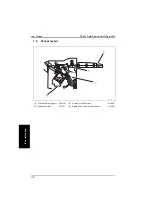
Page 90: ...eld Service Ver2 0 Sep 2004 4 2 IV Troublshoot ing 1 3 Sensor layout 1 Turnover Empty Sensor PC6 HO 3 Folding Position Sensor PI10 FN 2 Entrance Sensor PI1 FN 4 Staple Drive Home Position Sensor PI19 FN 3 1 4 2 4583fs4521c0 ...

Page 91: ...tected paper edge Relevant electrical parts Entrance Sensor PI1 FN Finisher Control Board PWB A FN Step Action WIRING DIAGRAM Control signal Location Electrical compo nents 1 Initial check items 2 PI1 FN I O sensor check PWB A FN CN16 FN 11 G 3 3 PWB A FN replacement E 6 Type Description horizontal trans port section mis feed detection The Turnover Empty Sensor PC6 HO is not unblocked even after t...

Page 92: ...Motor M7 FN has been driven during stapling operation Relevant electrical parts Folding Position Sensor PI10 FN Finisher Control Board PWB A FN Step Action WIRING DIAGRAM Control signal Location Electrical compo nents 1 Initial check items 2 PI10 FN I O sensor check PWB A FN CN16 FN 2 F 3 3 PWB A FN replacement E 6 Type Description Stapler section mis feed detection The Staple Drive Home Position ...

Page 93: ...iven period of time after the Folding Roller has started moving from a position not the home position C0B05 Paddle Motor malfunctions The Paddle Home Position Sensor PI2 FN is not unblocked even after the lapse of a given period of time after the Paddle has started moving from its home posi tion The Paddle Home Position Sensor PI2 FN is not blocked even after the lapse of a given period of time af...

Page 94: ...even after the lapse of a given period of time after the Rear Aligning Plate has started moving from its home position to a position out of the home position The Rear Aligning Plate Home Position Sensor PI5 FN is not blocked even after the lapse of a given period of time after the Rear Aligning Plate has started moving from a position out of the home position to the home position C0B4C Booklet Exi...

Page 95: ... response is received to a request made by the Fin isher within a given period of time during ordinary com munications There is no match in the checksum values of the backup data as checked twice The 24 V power source of the Punch Unit is OFF when an operation request is made from the Finisher C0B76 Punch Side Registration Motor malfunctions The Side Registration Home Sensor PI2P PK is not unblock...

Page 96: ... OFF and ON the Power Switch NOTE Before starting the troubleshooting in relation to the Punch Mechanism C0B7X be sure to turn OFF the Power Switch of the main unit C0BA0 Elevate Mechanism malfunctions The Exit Tray Home Position Sensor PI9 FN is not blocked even after the lapse of a given period of time after the tray has started moving up An encoder clock input is not detected within a given per...

Page 97: ...ked even after the lapse of a given period of time after the Folding Roller has started moving from a position not the home position Relevant electrical parts Folding Roller Home Position Sensor PI12 FN Transport Motor M1 FN Finisher Control Board PWB A FN Step Action WIRING DIAGRAM Control signal Location Electrical compo nents 1 Check the motor connectors for proper connection and correct as nec...

Page 98: ...ooklet Roller has started moving from its home position The Swing Guide Home Position Sensor PI3 FN is not blocked even after the lapse of a given period of time after the Booklet Roller has started moving from a position not the home position Relevant electrical parts Paddle Home Position Sensor PI2 FN Swing Guide Home Position Sensor PI3 FN Paddle Motor M2 FN Finisher Control Board PWB A FN Step...

Page 99: ...r the lapse of a given period of time after the Stapler Unit has started moving from a position not the home position Relevant electrical parts Slide Home Position Sensor PI18 FN Slide Motor M8 FN Finisher Control Board PWB A FN Step Action WIRING DIAGRAM Control signal Location Electrical compo nents 1 Check the motor and sensor connectors for proper connection and correct as necessary 2 Check th...

Page 100: ...ed even after the lapse of a given period of time after the Front Aligning Plate has started moving from a position out of the home position to the home position Relevant electrical parts Front Aligning Plate Home Position Sensor PI4 FN Front Aligning Motor M4 FN Finisher Control Board PWB A FN Step Action WIRING DIAGRAM Control signal Location Electrical compo nents 1 Check the motor and sensor c...

Page 101: ...d even after the lapse of a given period of time after the Rear Aligning Plate has started moving from a position out of the home position to the home position Relevant electrical parts Rear Aligning Plate Home Position Sensor PI5 FN Rear Aligning Motor M5 FN Finisher Control Board PWB A FN Step Action WIRING DIAGRAM Control signal Location Electrical compo nents 1 Check the motor and sensor conne...

Page 102: ...apse of a given period of time after the Booklet Exit Belt has started moving from a position not the home position during an initial operation The Exit Belt Home Position Sensor PI7 FN is not blocked even after the lapse of a given period of time after the Booklet Exit Belt has started moving from a position not the home position during an ordinary operation Relevant electrical parts Exit Belt Ho...

Page 103: ... the lapse of a given period of time after a folding operation has been started during an ordi nary operation The Folding Home Position Sensor PI11 FN is not blocked even after the lapse of a given period of time after a folding operation has been started and the sensor has been unblocked during an ordinary operation An encoder clock input is not detected within a given period of time during a fol...

Page 104: ...es sary 3 PI14 FN I O sensor check PWB A FN CN9 FN 5 I 5 4 M7 FN operation check when the Power Switch is turned OFF and ON PWB A FN CN6 FN 3 4 A 4 5 PWB A FN replacement E 6 Relevant electrical parts Folding Home Position Sensor PI11 FN Staple Folding Motor M7 FN Finisher Control Board PWB A FN Step Action WIRING DIAGRAM Control signal Location Electrical compo nents 1 Check the motor and sensor ...

Page 105: ...rol Board PWB A FN Step Action WIRING DIAGRAM Control signal Location Electrical compo nents 1 Check the motor and sensor connectors for proper connection and correct as necessary 2 Check the connector of motor for proper drive coupling and correct as neces sary 3 PI14 FN I O sensor check PWB A FN CN9 FN 5 I 5 4 M7 FN operation check when the Power Switch is turned OFF and ON PWB A FN CN6 FN 3 4 A...

Page 106: ...ions There is no match in the checksum values of the backup data as checked twice The 24 V power source of the Punch Unit is OFF when an operation request is made from the Finisher Relevant electrical parts Finisher Control Board PWB A FN Punch Control Board PWB B PK Step Action WIRING DIAGRAM Control signal Location Electrical compo nents 1 Turn OFF and ON the main switch 2 Check the connection c...

Page 107: ...moving from its home position The Side Registration Home Sensor PI2P PK is not blocked even after the lapse of a given period of time after the Punch Side Registration Unit has started moving from a position not the home position Relevant electrical parts Side Registration Home Sensor PI2P PK Punch Control Board PWB B PK Step Action WIRING DIAGRAM Control signal Location Electrical compo nents 1 C...

Page 108: ...l operation falls outside the threshold value range Relevant electrical parts Punch Home Position Sensor PI1P PK Punch Motor Clock Sensor PI3P PK Punch Motor M1P PK Punch Control Board PWB B PK Step Action WIRING DIAGRAM Control signal Location Electrical compo nents 1 Check the motor and sensor connectors for proper connection and correct as necessary 2 Check the connector of motor for proper dri...

Page 109: ...s Side Registration Home Sensor PI2P PK Punch Control Board PWB B PK Step Action WIRING DIAGRAM Control signal Location Electrical compo nents 1 Check the sensor connectors for proper connection and correct as necessary 2 PI2P PK I O sensor check PWB B PK J1006 PK 3 C 2 3 PWB B PK replacement C 1 Relevant electrical parts Punch Control Board PWB B PK Punch Trash Full Photo Sensor Board PWB E PK Pu...

Page 110: ...nal Location Electrical compo nents 1 Check the sensor connectors for proper connection and correct as necessary 2 PI15 FN I O sensor check PWB A FN CN15 FN 12 G 8 3 PWB A FN replacement E 6 Relevant electrical parts Exit Tray Home Position Sensor PI9 FN Shift Motor Clock Sensor PI17 FN Shift Motor M6 FN Finisher Control Board PWB A FN Step Action WIRING DIAGRAM Control signal Location Electrical ...

Page 111: ...recorded in it and writing operation is not correctly performed even with two retry sequences a total of three writing sequences Relevant electrical parts Finisher Control Board PWB A FN Step Action WIRING DIAGRAM Control signal Location Electrical compo nents 1 Disconnect and then connect the power cord to turn OFF and ON the main switch 2 Check the connectors for proper connec tion on the PWB A ...

Page 112: ...Trouble code FS 601 Field Service Ver2 0 Sep 2004 4 24 IV Troublshoot ing Blank page ...

Reviews:

Related manuals for FS-601