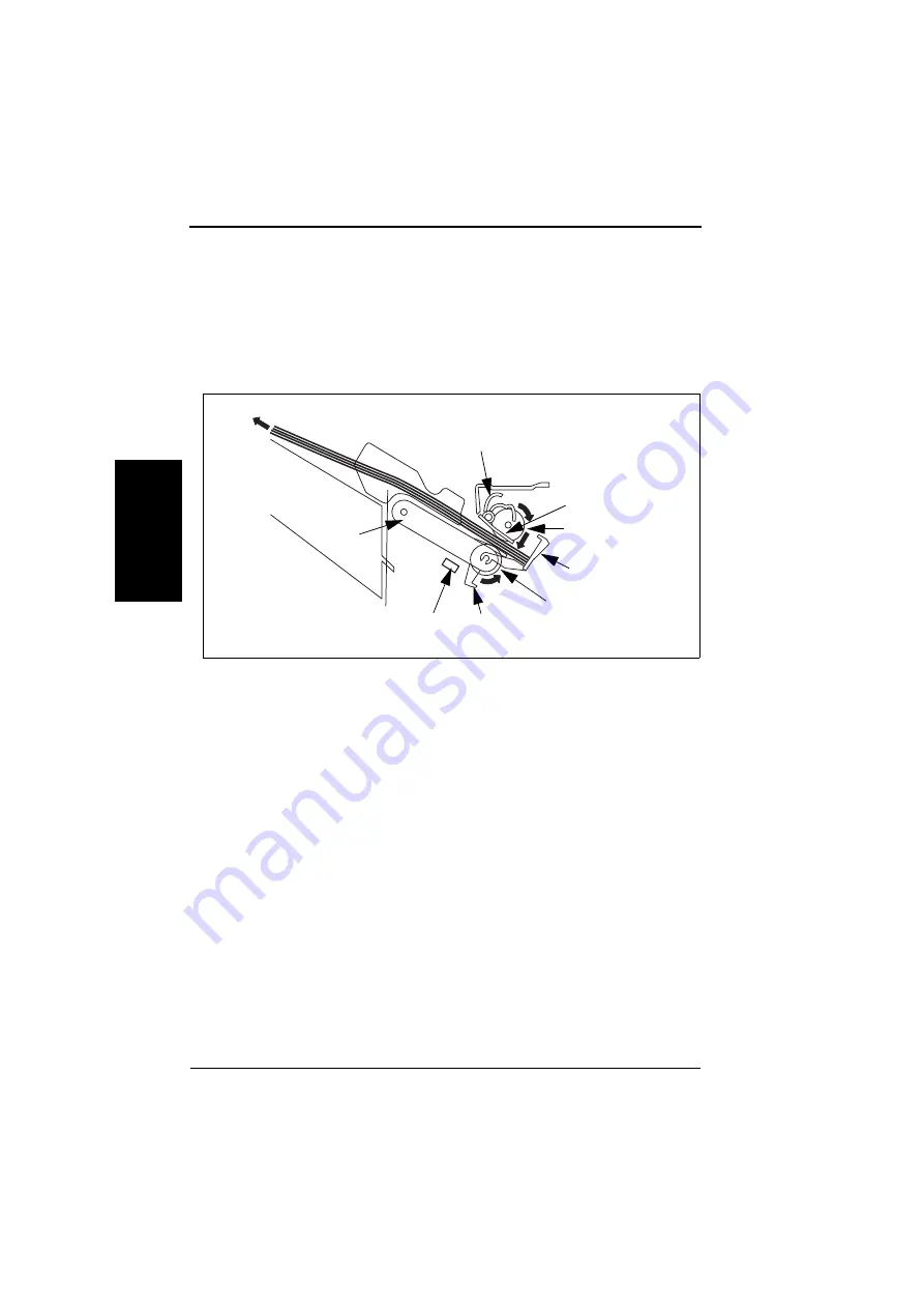
Mechanical operations
FS-601 Theory of Operation Ver2.0 Sep. 2004
2-12
II Co
mp
o
sit
io
n
/O
p
erat
io
n
4.2.8
Exiting operation
• The Paddle, driven by the Paddle Motor, makes the Swing Guide move down and then
the paper is taken up with the Upper, and Lower Exit Rollers.
• Next, the Exit Motor rotates in the forward direction to transport the paper taken up with
the Exit Rollers toward the Exit Section by the Exit Rollers and the Exit Belt.
• The Exit Belt Home Position Sensor turns OFF and then the Swing Guide moves up after
the Motor has been driven for a given number of pulses. The Exit Motor is driven to trans-
port a stack of paper with the Separators, of the Exit Belt, rotating in synchronization with
the Lower Exit Roller onto the Elevator Tray.
Paddle
Swing Guide
Upper Exit Roller
Stopper
Lower Exit Roller
Separator
Exit Belt Home Position
Sensor (PI7-FN)
Exit Belt
Elevator Tray
Summary of Contents for FS-601
Page 1: ...SERVICE MANUAL 2004 09 Ver 2 0 FS 601 THEORY OF OPERATION ...
Page 2: ......
Page 4: ......
Page 10: ...Product specification FS 601 Theory of Operation Ver2 0 Sep 2004 1 4 I Outline Blank page ...
Page 37: ...SERVICE MANUAL 2004 09 Ver 2 0 FIELD SERVICE FS 601 ...
Page 38: ......
Page 40: ......
Page 70: ...Other FS 601 Field Service Ver2 0 Sep 2004 2 22 I General II Maintenance Blank page ...
Page 88: ...Board switch FS 601 Field Service Ver2 0 Sep 2004 3 18 III Adjustment Setting Blank page ...
Page 112: ...Trouble code FS 601 Field Service Ver2 0 Sep 2004 4 24 IV Troublshoot ing Blank page ...


