FS-601 Field Service Ver2.0 Sep. 2004
Other
2-9
II
M
a
in
te
na
n
c
e
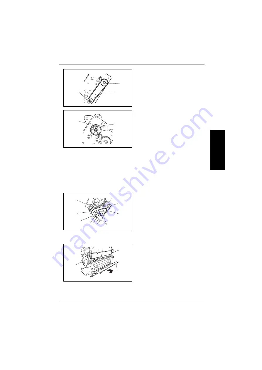
16.
Set the Timing Belt [27] to the Gear
[28] and Gear [29] with the Gear and
the Cam in the fixed condition.
17.
Install the Staple Position Confirm
Gear [32] in such a way that the blue
mark [30] of the Gear comes face to
face with the hole [31] in the frame.
NOTE
• The position in which the blue mark
meets face to face with the hole is
the home position for stapling. If
the Staple Jam Release Gear is
turned for some reason, this home
position will shift and the Staple
Cartridge will not come off. In this
case, the Staple Position Confirm
Gear plays a role of resuming the
stapling home position by referring
to the blue mark. Therefore, the
Gear should be set in place cor-
rectly.
18.
Remove the pin fixing the Gear and
the Cam to release them.
19.
Set the spring [33], the spacer [34],
the Staple Jam Release Gear [35],
the Timing Belt [36] and the Middle
Gear 1 [37], and fix them with two E-
Rings [38].
1.3.11
Saddle Section
1.
Remove the Front Cover.
☞
2.
Remove the Rear Cover.
☞
3.
Open the Jam Access Cover [1],
remove two screws [2], and remove
the Right Stay [3].
4.
Remove two screws [4], and remove
the Lever [5].
4583fs2512c0
[28]
[29]
[27]
4583fs2513c0
[30]
[31]
[32]
4583fs2514c0
[35]
[38]
[37]
[33]
[34]
[36]
[1]
[2]
[5]
[3]
[4]
[2]
4583fs2544c0
Summary of Contents for FS-601
Page 1: ...SERVICE MANUAL 2004 09 Ver 2 0 FS 601 THEORY OF OPERATION ...
Page 2: ......
Page 4: ......
Page 10: ...Product specification FS 601 Theory of Operation Ver2 0 Sep 2004 1 4 I Outline Blank page ...
Page 37: ...SERVICE MANUAL 2004 09 Ver 2 0 FIELD SERVICE FS 601 ...
Page 38: ......
Page 40: ......
Page 70: ...Other FS 601 Field Service Ver2 0 Sep 2004 2 22 I General II Maintenance Blank page ...
Page 88: ...Board switch FS 601 Field Service Ver2 0 Sep 2004 3 18 III Adjustment Setting Blank page ...
Page 112: ...Trouble code FS 601 Field Service Ver2 0 Sep 2004 4 24 IV Troublshoot ing Blank page ...


