Board switch
FS-601 Field Service Ver2.0 Sep. 2004
3-14
III
Ad
ju
stmen
t/
S
et
ti
n
g
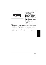
4.2.1
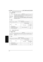
Adjustment of the sensor output
• Be sure to make this adjustment after replacing the Punch Control Board, the Side Reg-
istration Sensor (Photosensor Board or LED Board) or the Punch Dust Full Sensor
(Punch Dust Full Sensor Board or Punch Dust Full LED Board).
1.
Set the bits 1 through 4 of
DIPSW1001 on the Punch Control
Board as shown on the Left figure.
2.
Press SW1002 or SW1003 on the
Punch Control Board. The sensor
output will be automatically adjusted.
• When all LED1001, LED1002 and
LED1003 light up, the adjustment has
been completed.
3.
Set all bits of DIPSW1001 to OFF.
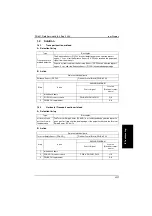
4.2.2
Registration of the number of punch holes
• In order for the Finisher to recognize the number of punch holes that can be achieved by
the installed Punch Unit, such number of punch holes is registered in the IC on the
Punch Control Board. Make this registration whenever the Punch Control Board has
been replaced.
• However, this registration is not necessary if the EEP-ROM used on an old board has
been reinstalled to a new board.
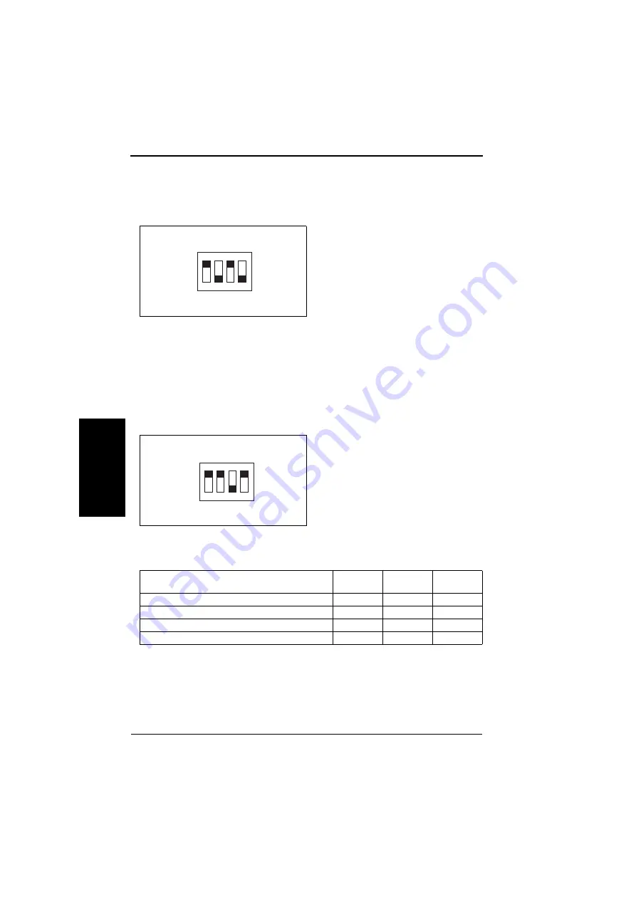
1.
Set the bits 1 through 4 of
DIPSW1001 on the Punch Control
Board as shown on the Left figure.
2.
Press SW1002 on the Punch Control Board to select the number of punch holes.
• Each time SW1002 is pressed, the following display changes in the descending order
shown below:
3.
Press SW1003 on the Punch Control Board twice. The number of punch holes will be
registered in the Punch Control Board.
• The pressing of SW1003 changes the steady lighting of the LED to flickering, and the
pressing of SW1003 again changes the flickering of the LED to steady lighting. This com-
pletes the registration.
4.
Set all bits of DIPSW1001 to OFF.
ON
1
2
3
4
4583fs3515c0
ON
1
2
3
4
4583fs3516c0
Number of punch holes
LED
1001
LED
1002
LED
1003
2 (Punch Unit J1)
ON
OFF
OFF
2/3 (Punch Unit K1)
ON
ON
OFF
4 (Punch Unit G1)
OFF
ON
OFF
4 (Punch Unit H1)
OFF
OFF
ON
Summary of Contents for FS-601
Page 1: ...SERVICE MANUAL 2004 09 Ver 2 0 FS 601 THEORY OF OPERATION ...
Page 2: ......
Page 4: ......
Page 10: ...Product specification FS 601 Theory of Operation Ver2 0 Sep 2004 1 4 I Outline Blank page ...
Page 37: ...SERVICE MANUAL 2004 09 Ver 2 0 FIELD SERVICE FS 601 ...
Page 38: ......
Page 40: ......
Page 70: ...Other FS 601 Field Service Ver2 0 Sep 2004 2 22 I General II Maintenance Blank page ...
Page 88: ...Board switch FS 601 Field Service Ver2 0 Sep 2004 3 18 III Adjustment Setting Blank page ...
Page 112: ...Trouble code FS 601 Field Service Ver2 0 Sep 2004 4 24 IV Troublshoot ing Blank page ...


