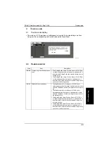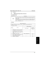
Trouble code
FS-601 Field Service Ver2.0 Sep. 2004
4-18
IV
T
rou
b
lsh
oot
in
g
2.3.8
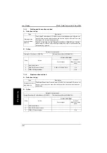
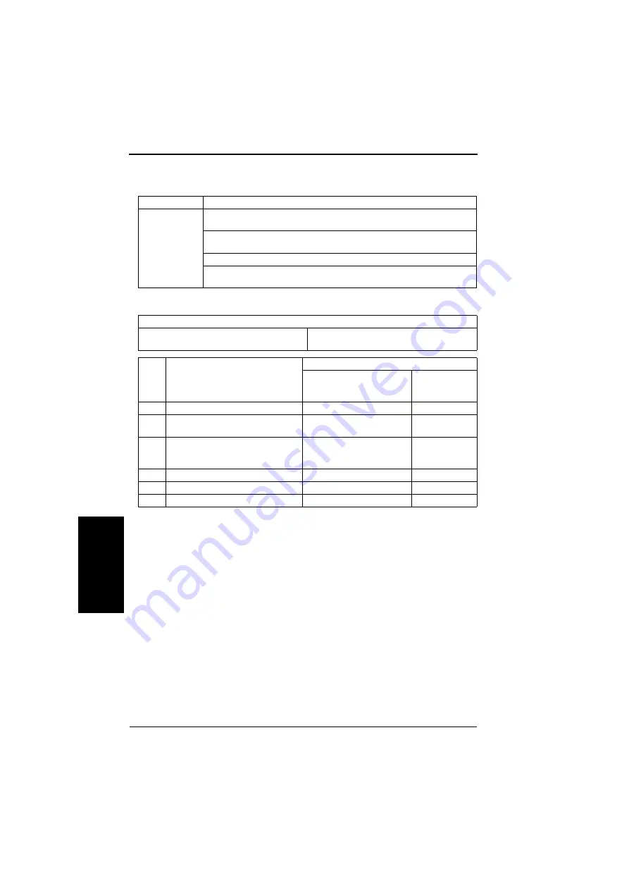
C0B75:Punch Control Board malfunctions
A. Detection timing
B. Action
Malfunction code
Description
C0B75
No response is received to a request made by the Finisher within a given period of
time during initial communications.
No response is received to a request made by the Finisher within a given period of
time during ordinary communications.
There is no match in the checksum values of the backup data as checked twice.
The 24 V power source of the Punch Unit is OFF when an operation request is
made from the Finisher.
Relevant electrical parts
Finisher Control Board (PWB-A FN)
Punch Control Board (PWB-B PK)
Step
Action
WIRING DIAGRAM
Control signal
Location
(Electrical compo-
nents)
1
Turn OFF and ON the main switch.
-
-
2
Check the connection condition between
the Punch Unit and PWB-A FN.
-
-
3
Measure the voltage between CN14-5
(+) and CN14-3 (-) of the PWB-A FN. Is
the voltage 24VDC?
-
-
4
Initialize Punch Unit EEP-ROM.
-
-
5
PWB-B PK replacement
-
C-1
6
PWB-A FN replacement
-
E-6
Summary of Contents for FS-601
Page 1: ...SERVICE MANUAL 2004 09 Ver 2 0 FS 601 THEORY OF OPERATION ...
Page 2: ......
Page 4: ......
Page 10: ...Product specification FS 601 Theory of Operation Ver2 0 Sep 2004 1 4 I Outline Blank page ...
Page 37: ...SERVICE MANUAL 2004 09 Ver 2 0 FIELD SERVICE FS 601 ...
Page 38: ......
Page 40: ......
Page 70: ...Other FS 601 Field Service Ver2 0 Sep 2004 2 22 I General II Maintenance Blank page ...
Page 88: ...Board switch FS 601 Field Service Ver2 0 Sep 2004 3 18 III Adjustment Setting Blank page ...
Page 112: ...Trouble code FS 601 Field Service Ver2 0 Sep 2004 4 24 IV Troublshoot ing Blank page ...

