Other
FS-601 Field Service Ver2.0 Sep. 2004
2-20
I Ge
n
e
ra
l
II
M
a
int
e
na
n
c
e
9.
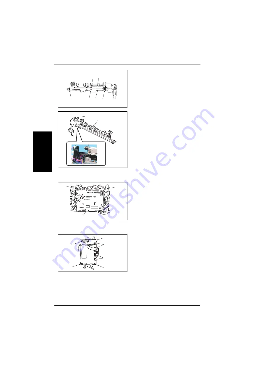
Remove four screws [11], and
remove the Sensor Unit (Upper) [12]
and the Sensor Unit (Lower) [13].
10.
Remove the spring[14].
11.
Remove the Punch Unit [16] from the
Side Registration Motor section [15].
1.3.22
Finisher Control Board
1.
Remove the Rear Cover.
☞
2.
Unplug all connectors on the Board,
and remove the screw [1].
3.
Release the PCB support [2], and
remove the Finisher Control Board
[3].
1.3.23
Punch Control Board
1.
Remove two screws [1].
2.
Unplug seven connectors [2], and
remove the Punch Control Board [3].
[11]
[11]
4583fs2589c0
[13]
[12]
[11]
[11]
[16]
[15]
4583fs2590c0
[14]
[2]
[1]
[3]
4583fs2592c0
[1]
[1]
[3]
[2]
[2]
4583fs2591c0
[2]
[2]
Summary of Contents for FS-601
Page 1: ...SERVICE MANUAL 2004 09 Ver 2 0 FS 601 THEORY OF OPERATION ...
Page 2: ......
Page 4: ......
Page 10: ...Product specification FS 601 Theory of Operation Ver2 0 Sep 2004 1 4 I Outline Blank page ...
Page 37: ...SERVICE MANUAL 2004 09 Ver 2 0 FIELD SERVICE FS 601 ...
Page 38: ......
Page 40: ......
Page 70: ...Other FS 601 Field Service Ver2 0 Sep 2004 2 22 I General II Maintenance Blank page ...
Page 88: ...Board switch FS 601 Field Service Ver2 0 Sep 2004 3 18 III Adjustment Setting Blank page ...
Page 112: ...Trouble code FS 601 Field Service Ver2 0 Sep 2004 4 24 IV Troublshoot ing Blank page ...


