background image

E-1

LU-302 

Large Capacity Unit

INSTALLATION MANUAL

A87V-9550-00

Applied Machines: C368/C308

COLOR MFP: 36 ppm/30 ppm

Product Code: A7PU/A7PY

Caution:

Lifting the machine in an awkward position or 
transporting it in a poorly balanced position could 
result in personal injury. When transporting the 
machine, assign an adequate number of persons 
to the job and ensure that each person can take a 
good position of not being excessively loaded. 
(mass: approx. 18 kg (39-3/4 lb))

1. Accessory parts


Note:

    • Before installing the large capacity unit the 

Paper Feed Cabinet PC-410, PC-210, or PC-
110 needs to be installed in advance.

    • This manual provides the illustrations of the 

accessory parts and machine that may be 
slightly different in shape from yours. In that 
case, instead of the illustrations, use the 
appearance of your machine to follow the 
installation procedure. This does not cause any 
significant change or problem with the proce-
dure.

    • If none of the later steps instruct you to use the 

parts including screw and cover that you 
removed following the instructions described in 
this manual, discard them.

No.

Name

Shape

Q’ty

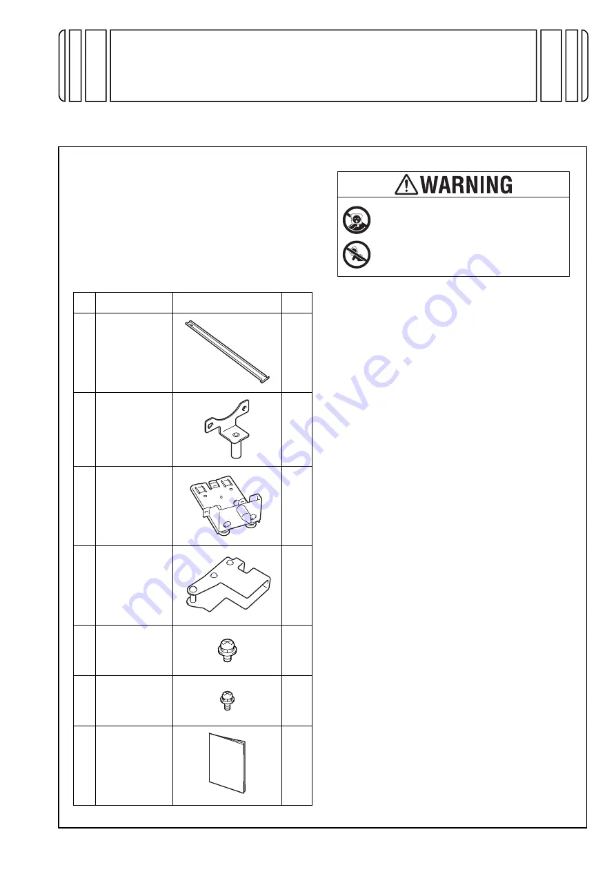
1. Rail

1

2. Mounting 

bracket A

1

3. Mounting 

bracket B

1

4. Mounting 

bracket C

2

5. Screw A 

(4 x 8 mm)

3

6. Screw B 

(3 x 8 mm)

8

7. Installation 

manual 

1 set

Keep this bag away from babies and 
children. Do not use in cribs, beds, 
carriages, or playpens.

The thin film may cling to nose and 
mouth and prevent breathing. This bag is 
not a toy.

Summary of Contents for LU-302

Page 1: ...nual provides the illustrations of the accessory parts and machine that may be slightly different in shape from yours In that case instead of the illustrations use the appearance of your machine to follow the installation procedure This does not cause any significant change or problem with the proce dure If none of the later steps instruct you to use the parts including screw and cover that you re...

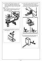
Page 2: ...rom the right side of the main body 4 Slide out the drawer of the paper feed cabinet Note For the Paper Feed Cabinet PC 210 or PC 110 slide out both upper and lower drawers 5 Remove the front right cover from the paper feed cabinet Four screws Note Since connector s are connected to the paper feed cabinet cover be careful not to strongly pull the cover when removing it 6 Remove the rear right cove...

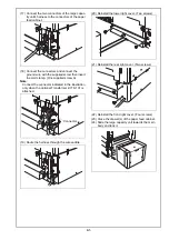
Page 3: ...ht cover using nippers 9 Remove the two knockouts from the rear right cover using nippers 10 Remove the two knockouts from the lower right cover using nippers 11 Install the supplied mounting brackets C onto the two places Two supplied screws B each 12 Install the supplied mounting bracket B onto the supplied rail ...

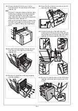
Page 4: ...secured in the correct position install the rail with the supplied screws Four supplied screws B 14 Insert the mounting bracket A into the round hole on the rail 15 Hold up the mounting bracket A and insert the rail Insert the protrusion of the mounting bracket A into the round hole on the base of the large capacity unit Two supplied screws A 16 Route the harness of the large capacity unit through...

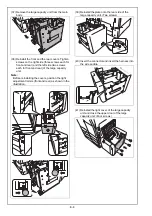
Page 5: ...ed screw A Note Connect the connector indicated in the illustration only when the optional Transformer kit TK 101 is attached 19 Route the harness through the wire saddle 20 Reinstall the lower right cover Two screws 21 Reinstall the rear right cover Two screws 22 Reinstall the front right cover Four screws 23 Close the drawer s of the paper feed cabinet 24 Slide the large capacity unit towards th...

Page 6: ... perform Load ing paper without making any height adjust ment 26 Remove the large capacity unit from the main body and open the upper door of the large capacity unit 27 Remove the right cover of the large capacity unit Four screws 28 Disconnect the connector and remove the har ness from the wire saddle 29 Loosen the screws on the right side three screws each for front and rear and the left side tw...

Page 7: ...ide adjustment roller s screws front and rear counterclockwise the overall length of the right adjustment roller s legs is shortened and therefore the right side of the unit is lowered Until the clearance 3 0 mm 2 0 mm is ensured between the main body and the large capacity unit make the height adjustment of the large capacity unit 35 After the height adjustment turn the screws so that the left si...

Page 8: ... rear of the large capacity unit Note Before reinstalling the covers position the right adjustment rollers front and rear as shown in the illustration 39 Reinstall the plate onto the rear side of the large capacity unit Two screws 40 Insert the connector and insert the harness into the wire saddle 41 Reinstall the right cover of the large capacity unit and close the upper door of the large capacit...

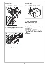
Page 9: ...or of the large capacity unit Affixing the label Affix the paper size label supplied with the main body to the positions shown in the illustration 3 Configuration procedures Making settings for paper size 1 Plug the power cord into the power outlet and turn ON the power switch 2 Display the Service Mode screen For details of how to display the Service Mode screen see the service manual 3 Touch Sys...

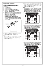
Page 10: ... key does not allow the measurement to fall within the specified range perform the following steps 7 Open the upper door of the large capacity unit Loosen the adjustment screws four screws and make an adjustment by moving the paper guide side plates to the left or right Note During adjustment in order to keep the same dis tance between the paper guide side plates place a sheet of paper between the...

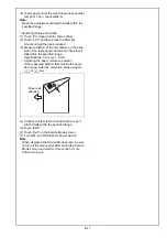
Page 11: ...k that it falls within the specified range Specifications 3 0 mm 1 0 mm Adjusting the paper reference position If the measured width A falls outside the speci fied range enter the correction value using the or key 4 Produce another test print and check to see if width A falls within the specified range 5 Touch END 6 Touch Exit on the Service Mode screen 7 Turn OFF and ON the Main Power Switch Note...

Reviews: