background image

PC-401

– 6 –

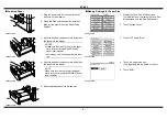
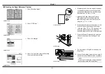
Checking the Paper Reference Position

1. Touch “Machine Adjust.”

4036P031CA

2. Touch “PRT Area.”

4036P036CA

3. Touch “Left Margin.”

4348P023CA

4. Touch “3rd” and then press the Start key.

A test print will be produced.

4348P025CA

5. Measure width A from the edge of the paper 

to the pattern printed on the test print and 
check that it falls within the specified range.
Specifications: 3.0 mm ± 1.0 mm

Adjusting the Paper Reference Position 
If the measured width A falls outside the 
specified range, enter the correction value 
using 

the  

or  

key.

6. Produce another test print and check to see 

if width A falls within the specified range.

*

If the use of the 

 or 

 key does not 

allow the measurement to fall within the 
specified range, perform the following steps.

C4658U028AA

A

Paper Exit 

Direction

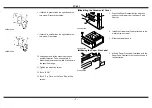
7. Press the Drawer Release button and then 

slide out the drawer from the Paper Feed 
Cabinet.

4348U010AA

8. Pull the release of Right Door and open the 

Right Door.

9. Loosen the adjusting screw and turn screw D 

clockwise or counterclockwise as necessary.

NOTE

Use care not to damage or dent the paper 
path surface inside the Right Door.

4348U011AA

Summary of Contents for PC-401

Page 1: ...Printed in Japan INSTALLATION MANUAL PC 401 for Product Code 4036 Paper Feed Cabinet NOTES Before installing be sure to unplug the power cord of the machine Keep all packing materials out of the reach...

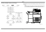
Page 2: ...llation procedures for each option follow the instructions given in the corresponding Installation Manual and perform the procedures correctly Electron System Options PC 101 PC 201 DK 501 DF 601 AD 50...

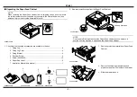
Page 3: ...t peel off the tape that fixes the Paper Feed Cabinet hookup harness in position until the machine is attached to the Paper Feed Cabinet 1 Fixing Leg 4 2 Fixing Leg Cover 4 3 Fixing Bracket 4 4 Should...

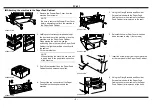
Page 4: ...load to the paper take up section of the machine 4348U117AA 3 Peel off the tape that fixes the Paper Feed Cabinet hookup harness in position 4 Connect the two connectors of the Paper Feed Cabinet hoo...

Page 5: ...llustration 2 Pieces NOTES Insert the Fixing Leg Covers in the direc tion shown by arrow until they click into position Insert the Protruded Portions of the cover shown by the arrows into the Fixing L...

Page 6: ...per level indicator Correct any curl in the paper before load ing 4348U012AA 4 Align the edges of the paper stack and place the stack into the drawer NOTE Make sure that the top level of the paper sta...

Page 7: ...outside the specified range enter the correction value using the or key 6 Produce another test print and check to see if width A falls within the specified range If the use of the or key does not allo...

Page 8: ...t Then check width A Make the adjustment until width A falls within the specified range 11 Tighten the adjusting screw 12 Touch END 13 Touch Fin Time on the Tech Rep Mode screen 1 Press the Paper Desc...

Reviews: