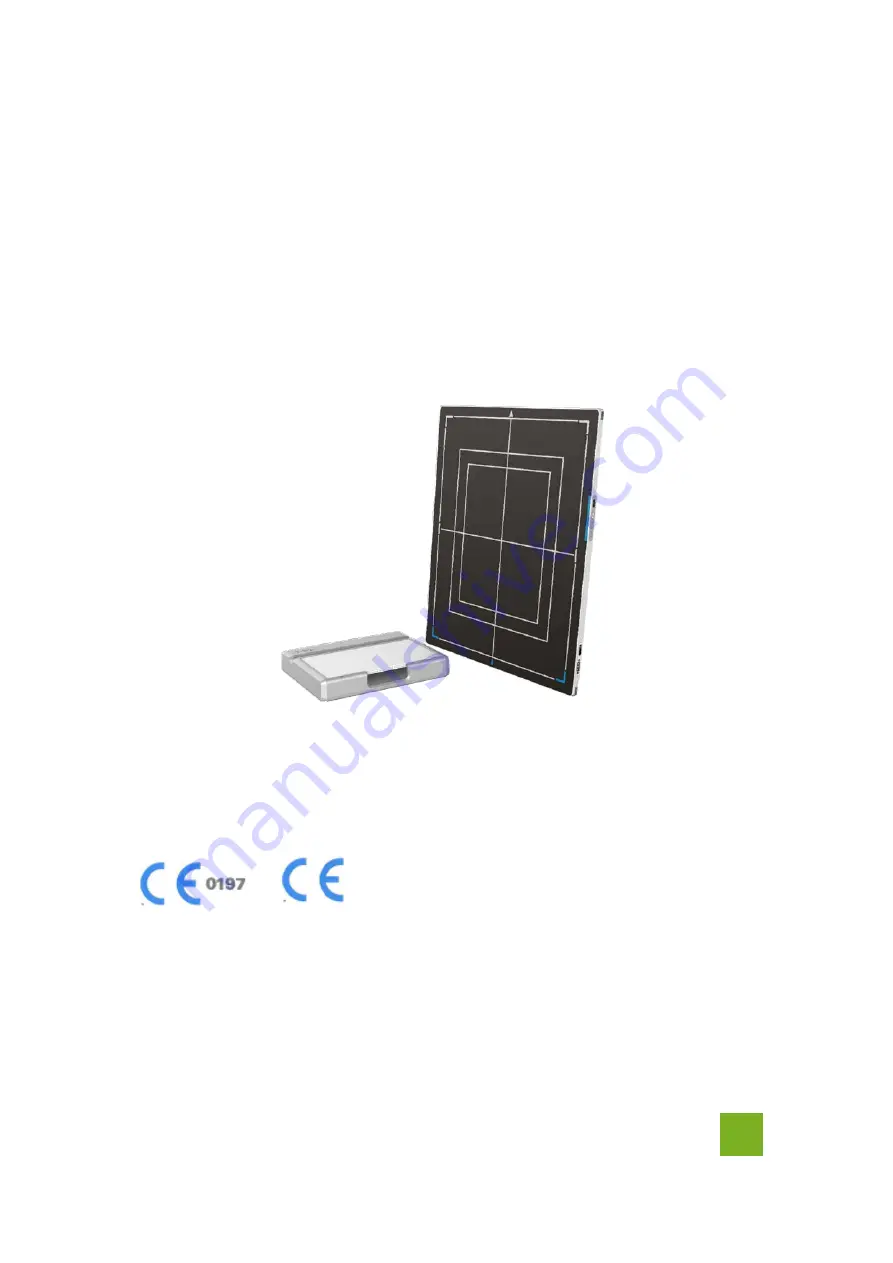
background image

DIRECT DIGITIZER

SKR 4000

User Manual

Document Version: 00

Document ID: ACNNBA01EN00

Release Date: 2019-05-08

Before operating, please read this user manual and pay attention to all safety precautions.

Please ensure that this user's manual is properly maintained so that it can be accessed at any time

(reserve).

Please use it correctly on the basis of full understanding of the content.

E

Summary of Contents for SKR 4000

Page 1: ...e Date 2019 05 08 Before operating please read this user manual and pay attention to all safety precautions Please ensure that this user s manual is properly maintained so that it can be accessed at any time reserve Please use it correctly on the basis of full understanding of the content E ...

Page 2: ......

Page 3: ...of the equipment 1 Read all of the instructions in user manual before operation Give particular attention to all safety precautions 2 Only a physician or a legally certified operator could use the product 3 The product should be maintained in a safe and operable condition by maintenance personnel 4 Use computers and image display monitors complying with IEC 60601 1 or IEC 60950 1 For details consu...

Page 4: ...the product 2 KONICA shall not be liable to any damage loss or injury arising from unauthorized modifications repairs or alterations to the product or failure to strictly comply with KONICA operating and maintenance instructions 3 KONICA shall not be liable for any damage or loss arising from the use of any options or consumable products other than those dedicated as Original products by KONICA Te...

Page 5: ... of the product may cause property damage This is used to indicate a prohibited operation This is used to indicate an action that must be performed This is used to indicate important operations and restrictions This is used to indicate operations for reference and complementary information This symbol indicates the name and address of manufacturers Labels and markings on the equipment The contents...

Page 6: ... the name and address of manufacturer This symbol is used to indicate consultation of the user guide for general information Safety Signs please refer to user manual for safety instructions Safety Signs Dangerous Voltage Handled with care This symbol indicates operational temperature limits This symbol indicates storage temperature limits This symbol indicates the product radiates wireless signal ...

Page 7: ...ication Package symbol fragile Package symbol keep away from sunlight Package symbol keep dry This symbol indicates the humidity limits Keep the product up right Do not roll the transportation package This symbol indicates stacking limit number Type B applied part IPX1 for working surface only ...

Page 8: ...sential performance 19 2 5 1 Application specification 19 2 6 The relative position between patient and detector 20 2 7 Product Components 20 2 8 Components Description 22 2 8 1 Detector 22 2 8 2 Battery 23 2 8 3 Battery Charger 24 2 9 Product Specification 25 2 9 1 Detector 25 2 9 2 Battery 26 2 9 3 Battery Charger 27 2 9 4 Power supply 27 2 9 5 AP Router Optional 27 2 9 6 Wireless Communication ...

Page 9: ...ower 32 3 1 3 Booting Up 33 3 1 4 Button Function 35 3 2 Battery Charger Installation 36 3 3 Battery lock and activation 36 3 4 Software Installation 37 3 5 Panel Infrastructure 37 3 5 1 Wireless Client Mode 38 3 5 2 Wireless AP Mode 42 4 OPERATION 48 4 1 Main Operation 48 4 1 1 Software Mode 48 4 1 2 Inner2 Mode 50 4 1 3 Freesync Mode 52 4 2 Connection Build 53 4 3 Panel Configuration 54 4 4 Corr...

Page 10: ... Correction and Calibration management 65 4 8 Firmware Update 66 4 8 1 MCU Update 66 4 8 2 FPGA Update 69 4 8 3 ARM Update 71 4 8 4 ALL FIRMWARE Update 73 4 9 Short cut 73 4 10 Software 74 4 10 1 Main GUI 74 4 10 2 Message Box 75 4 10 3 Configuration GUI 76 4 11 List of the HAZARDOUS SITUATIONS resulting from a failure of the IT NETWORK 79 5 REGULATORY INFORMATION 80 5 1 Medical equipment safety s...

Page 11: ... MINOLTA INC 9 6 TROUBLE SHOOTING 86 7 SERVICE INFORMATION 87 7 1 Product Lifetime 87 7 2 Regular Inspection and Maintenance 87 7 3 Repair 87 7 4 Replacement Parts Support 87 APPENDIX A INFORMATION OF MANUFACTURES 88 ...

Page 12: ...l Otherwise it may result in fire or electric shock Do not handle the product with wet hands You may experience electric shock that could result in death or serious injury Do not place heavy object on cables and cords Do not pull bend bundle or step on them to prevent their sheath from being damaged and do not alter them neither Doing so may damage the cords which could result in fire or electric ...

Page 13: ...or electric shock Do not hit or drop the product The product may be damaged if it receives a strong jolt which may result in fire or electric shock if it is used without being repaired Do not put the product and pointed objects together The product may be damaged If so it should be used in bucky Have the patient take a fixed posture and do not let the patient touch parts unnecessarily If the patie...

Page 14: ... in any of the locations listed below Doing so may result in failure malfunction falling fire or injury Close to facilities where water is used Where it will be exposed to direct sunlight Close to the air outlet of an air conditioner or ventilation equipment Close to heat source such as a heater Where the power supply is unstable In a dusty environment In a saline or sulfurous environment Where te...

Page 15: ...tact with blood or other body fluids Doing so may result in fire or electric shock In such a situation protect the equipment with a disposable cover as necessary Turn OFF the power and pull out the plug to each piece of equipment for safety when not used CAUTION Handling Handle the product carefully Do not submerge the product in water Only working surface meets IPX1 The internal image sensor may ...

Page 16: ...esulting in injury to user or patient or may flip over resulting in damage to the inner device Keep the same load on the product when acquiring image The image will be incorrect CAUTION Do not close to fire do not use in high temperature Do not invert positive and negative pole Do not contact with metal in case of short circuit Do not insert sharp objects into battery Do not beat battery Do not st...

Page 17: ...cur in the quality of captured images When an air conditioner is used be sure to raise lower the temperature gradually to prevent condensation The product should be warmed up for 15 minutes before exposure or updating the gain map and defect map Make sure exposure rate is over 900nGy s 70KV Make sure wave form of the energy going to the X ray tube is square not pulse Be cautious with circumstance ...

Page 18: ...n For details on how to sterilize consult a specialist Do not spray the product directly with disinfectants or detergents Wipe it with a cloth slightly damped with a neutral detergent Do not use solvents such as benzene and acid Doing so may damage the surface of the product It s recommended to use a waterproof non woven cover as the isolated layer between product and the blooding patient Applied ...

Page 19: ...18 2 2 Model 18 2 3 Characteristic 18 2 4 Intended use essential performance application specification 19 2 5 Essential performance 19 2 6 The relative position between patient and detector 20 2 7 Product Components 20 2 8 Components Description 22 2 9 Product Specification 25 2 10 IT network 30 ...

Page 20: ...sed as a real portable panel 2 1 Scope This manual contains information about the SKR 4000 Information in the manual including the illustrations is based on prototype If your configuration does not have any of these items information about these items does not apply to your panel SKR 4000 Share SKR 4000 for different Radiography modality like an IP plate 2 2 Model Product Type SKR 4000 Product ser...

Page 21: ...ide hardware and software support for integration of system This panel is not intended for mammography and extra oral X ray applications which are covered by IEC60601 2 63 2 5 Essential performance According to the SKR 4000 series intended use and the result of risk management getting imaging and function of data transmission is defined as essential performance Getting qualified dark image proves ...

Page 22: ... detector Pay attention to the relative position of patient and detector the recommended position as shown below Otherwise the image is prone to abnormal light lines 2 7 Product Components SKR 4000 comes with both DC power supply and battery package Once powered on it would build a connection with Workstation through Ethernet cable only for service or Wireless connection Item Description SKR 4000 ...

Page 23: ...General Description KONICA MINOLTA INC 21 Medical Adapter 1 pcs DC 24V Battery 2 pcs Battery pack Ethernet Cable Only for service 1pcs 3 5 m Gigabit Ethernet Cable 1pcs 3 m AC Power Cable 1 pcs ...

Page 24: ...RECT DIGITIZER User Manual 22 KONICA MINOLTA INC DC Power Cable 1 pcs 3 5 m Battery Charger 1pcs CD Rom 1pcs Gain correction data Defect correction map SDK Manual 2 8 Components Description 2 8 1 Detector AB CDE F ...

Page 25: ...B Ethernet Port Gigabit Ethernet port C Detector Indicator Detector indicator of control panel D Power Button Power button of control panel E Mode Button Mode switch F Antenna Antenna 2 8 2 Battery Item Name Description A Battery Label B Battery Interface 8 Pin Battery connector C Pilot Pin D Indicator Installation direction indicator ...

Page 26: ...nterface C 5 Pin Battery connector D Indicator The indicator definition is as follow E The limit ball plug F Hand Pull Position G AC Jack 220V AC input The battery charger indicator definition A B C Item Name Description A Power Indicator B Charging Indicator C Charge Full Indicator X Indicator Lighting Status Operating Status All off No power input A indicator on AC Power input Multiple batteries...

Page 27: ...harging at the same time is prohibited if charging at the same time the charger will automatically stop 2 9 Product Specification 2 9 1 Detector Item Specification Model SKR 4000 Image Sensor a Si Amorphous Silicon TFT Pixel Size 150 μm Active Array 2304 x 2800 Active Area H x V 345 6mm x 420mm Gray scales 16bit Spatial Resolution 3 3 Lp mm Image Acquisition Time Wireless Both AP mode and Client m...

Page 28: ...b Max 11Mbps 802 11a g Max 54Mbps 802 11n Max 300Mbps MIMO 2x2 802 11ac Max 867Mbps MIMO 2x2 2 9 2 Battery Item Specifications Model Battery KV Rated Capacity Typ 4180mAh Discharge 0 2C Nominal Voltage 10 8V Charge Voltage 12 6 0 05V Discharged End Voltage 9V Charging Method CC CV Operating Temperature Charge 0 60 Discharge 10 60 Storage Temperature 3 month 20 45 6 month 20 35 Relative Humidity 5 ...

Page 29: ...SKR 4000 supports both DC Power and Battery package input Item Specifications DC Power 24V DC 0 75A Battery Package 10 8V DC 1 6A The product must be used with the approved adaptor whose CB certificate number is SG PSB MD 00191 2 9 5 AP Router Optional SKR 4000 do not include AP Router Users can choose AP Router as they wish however specification below is a requirement Item Specifications Wireless...

Page 30: ...ed States 19 Europe 8 Japan Data Transmission Rate 802 11b Max 11Mbps 802 11a g Max 54Mbps 802 11n Max 300Mbps MIMO 2x2 802 11ac Max 867Mbps MIMO 2x2 Modulation 802 11b CCK DQPSK DBPSK 802 11a g 64 QAM 16 QAM QPSK BPSK 802 11n 64 QAM 16 QAM QPSK BPSK 802 11ac 256 QAM 64 QAM 16 QAM QPSK BPSK Transmission Power Max 17dBm Security WPA WPA PSK WPA2 WPA2 PSK WEP 64bit 128bit Antenna 2 Dual Band inner a...

Page 31: ...e change Humidity Atmospheric Pressure Pressure Change Operating 5 35 1k min 10 90 RH 700 1060hPa 10kp min 1kp 1 0197E 5Pa Storage 20 55 1k min 5 95 RH 700 1060hPa 10kp min 1kp 1 0197E 5Pa The SKR 4000 serial detectors shall operate at an altitude specified not more than 3000m the environment is only for detector ...

Page 32: ...Vision and standard kilomaga network agreement is just data package the former data package from 4096 to 16224 bytes the latter just 1440 bytes 2 10 5 Intended information flow Intended information flow of FPD via IT network include data and command Hazardous situations resulting from a failure of the IT network 1 Failure of completing essential performance 2 Failure of finishing configuration of ...

Page 33: ...allation 32 3 1 1 Attach Battery Pack 32 3 1 2 Attach DC Power 32 3 1 3 Booting Up 33 3 1 4 Button Function 35 3 2 Battery Charger Installation 36 3 3 Battery lock and activation 36 3 4 Software Installation 37 3 5 Panel Infrastructure 37 3 5 1 Wireless Client Mode 38 3 5 2 Wireless AP Mode 42 ...

Page 34: ...r is on Panel would be activated immediately If none of battery and DC power is on SKR 4000 would power off Please see below for battery installation Make sure that the connectors on the battery package are pointed to the cave in battery compartment Slide battery package into battery compartment Make sure battery capacity overpass 10 Slide the battery lock lever 3 1 2 Attach DC Power Please see be...

Page 35: ... 3 Booting Up On the control panel user can press power button to power on off If panel is powered off user can press the button for 4 seconds to power on when battery is inserted and battery capacitor is no less than 10 or DC power is connected If panel is powered on user can press the button for 4 seconds to shut down On the other hand it can also be used as reset inner control IC when button is...

Page 36: ... Green and Orange Blinking Power OFF 20 and 95 YES Green Fast Blinking Power OFF 95 and 100 YES OFF Power OFF 100 YES Link indicator is as table Link Indicator Lighting Status Description OFF Shut down wired connection broken and wireless connection not ready Blue ON Client mode wireless connection is built AP mode wireless AP is ready Green ON Wired Connection is built Status indicator is as tabl...

Page 37: ...m ship mode Triple Click No Action Release after two short presses interval 1s Forced Restart Power ON Long Hold No Action Hold for more than 7 seconds when the POWER indicator is OFF and then ON Release Power Key Enter Exit Sleep Mode Double Click No Action Release after two short presses interval 1s Power OFF Short Hold No Action Hold for 4 seconds Release Power Key when the POWER indicator is O...

Page 38: ...nt 3 3 Battery lock and activation To ensure the safety of the battery during transportation or storage the battery can be set to ship mode that is the battery is locked without voltage output So it needs to exit ship mode before using the battery for the first time Two ways to enter ship mode Item Steps factory configuration Web write in Power the panel with adaptor and turn on it then connected ...

Page 39: ...imes to exit ship mode Charger Power on charger Insert the battery into the charger for 3 5s to exit ship mode 3 4 Software Installation In the case of iDetector not work please install Microsoft NET Framework 4 5 first then install vcredist_x86_2013 or vcredist_x64_vs2013 iDetector should not be used for terminal hospital 3 5 Panel Infrastructure SKR 4000 supports two connection modes as follows ...

Page 40: ... Wireless Client mode configuration user has to finish actions listed below Configuration of External wireless AP Connect one end of Gigabit Ethernet Cable to Workstation Connect another end to LAN port of External wireless AP Open local network management interface Open local network configuration ...

Page 41: ...Installation KONICA MINOLTA INC 39 open IPV4 setting IP setting Network mask setting Select Obtain an IP address automatically Open browser and type 192 168 1 1 Log into external wireless AP ...

Page 42: ... Wi Fi environment and choose a relatively clean channel Configure 5GHz wireless network SSID NETGEAR_BIG_50 Security WPA2 PSK Password 12345678 Channel Please check the current Wi Fi environment and choose a relatively clean channel LAN setup Configure LAN IP address IP address 192 168 8 1 Subnet Mask 255 255 255 0 External wireless AP reboot Apply above settings and reboot your wireless router ...

Page 43: ...er Wired Cable or Infrared device can be used to configure detector in wireless client mode The wired connection should be used by the service operator only To start configuration with wired cable It is necessary to finish 3 4 1 1 then proceed to the steps below Connect panel to Workstation with Ethernet Cable like 3 4 1 Click Detector Click Wifi Click Read Config Choose Client mode ...

Page 44: ...tatus numericl value occurred means the link is up and available Since we have chosen default SSID and password it would connect to wireless AP immediately after powered on next time 3 5 2 Wireless AP Mode To complete wired connection configuration user has to finish actions listed below Configuration of detector Either Wired cable or Infrared device can be used to configure panel wireless AP mode...

Page 45: ...o Workstation with Ethernet Cable like 3 4 1 Click Detector Select wifi Choose AP mode Click Read Config to get default setting Change SSID and password setting make sure SSID is different from other already exist Change channels and frequency setting ...

Page 46: ...ing Click Channel and choose a clean frequency and channel Click write config Do not remove wired cable until FPD status from Busy become Ready Since we have chosen default SSID and password it would connect to wireless AP immediately after powered on next time Configuration of external wireless card ...

Page 47: ...Installation KONICA MINOLTA INC 45 Open local wireless signal list Select SSID which belongs to detectors Input password and log into system Open wireless card configuration ...

Page 48: ...R 4000 DIRECT DIGITIZER User Manual 46 KONICA MINOLTA INC open IPV4 setting IP setting Network mask setting IP address 192 168 8 188 Subnet mask 255 255 255 0 Open SDK and choose product start connection ...

Page 49: ...54 4 4 Correction and Calibration Template Generation 55 4 5 Image Check and upload 60 4 6 Defect Template Check and Modification 61 4 7 Correction and Calibration Management 64 4 8 Firmware Update 66 4 9 Short cut 73 4 10 Software 74 4 11 List of the HAZARDOUS SITUATIONS resulting from a failure of the IT NETWORK 79 ...

Page 50: ...nel should build synchronization with X ray generator SKR 4000 is born with four ways to acquire x ray image which is Software Mode Inner2 Mode and FreeSync Mode 4 1 1 Software Mode 4 1 1 1 Block Diagram Software mode is the basic way to acquire x ray image Please see figure below for general feature Workstation Inner2 HVG Tube Workstation is a host device installed with iDetector and SDK Chapter ...

Page 51: ... diagram below for details Workstation Inner2 HVG Tube 1 Workstation receives prep request send command Clear to panel 2 Panel receives clear from workstation starts clearing leakage of panel Meanwhile panel send a message to workstation Exposure Prohibited 3 Panel finishes Clear and send a message to workstation Exposure Enable 4 Workstation shows Exposure Enable on the IDetector s message bar to...

Page 52: ...tion 11 Panel completes image acquisition and begins to send data to workstation 12 Workstation receives all image data from panel which are after calibration if Hardware calibration is on 4 1 2 Inner2 Mode 4 1 2 1 Block Diagram Workstation Inner2 HVG Tube Workstation is a host PC device installed with iDetector and SDK Chapter 3 has described how to establish connection between panels and worksta...

Page 53: ...2 X ray 3 4 5 1 Workstation receives prep request 2 X ray generator is ready for X ray shooting and begins to release X ray 3 Panel starts uploading Pre dark image and Light image to Workstation for preview If hardware offset is selected panel would do offset first and then upload preview image 4 Panel starts uploading Post dark image to Workstation If hardware offset is chosen panel would do corr...

Page 54: ...scribed how to establish connection between panel and Workstation In FreeSync mode User doesn t interact with Workstation After shooting images would be shown on screen immediately 4 1 3 2 Work Flow Check SDK to make sure panel is ready Shoot X ray X ray sensor in panel triggers panel to stop flushing the panel After fixed time panel starts image acquisition Wait for image uploaded ...

Page 55: ...lected panel would do offset first and then upload preview image 2X2 binning 4 Panel starts uploading Post dark image to Workstation If hardware offset is chosen panel would do correction and calibration first then upload processed image to Workstation 5 Workstation receives Exposure Enable from Panel 4 2 Connection Build Open SDK and choose product start connection Confirm the IP address and the ...

Page 56: ... IP address is not allowed to operate panel after the first one connected If there is no command transmission between panel and Workstation over 5 minutes panel releases access authority 4 3 Panel Configuration Choose iDetector menu related modules Acquire module related setting such as loading correction and calibration template acquiring images SDK module related setting such as IP address Detec...

Page 57: ...mage 4 4 Correction and Calibration Template Generation The correction and calibration should be performed after installation and it is recommended to perform the new correction and calibration after any major change on the system settings and hardware configuration On the other hand it is also recommended to do the correction and calibration in each 6 months 4 4 1 Pre offset Template Generation I...

Page 58: ...SKR 4000 DIRECT DIGITIZER User Manual 56 KONICA MINOLTA INC Select Calibrate Click Start Generate Templates Click Create Offset Click Start create offset template file It will show Offset Map Generating ...

Page 59: ...in Calibration Template Generation Before Gain template generating make sure SID1 2m no copper is required the GUI of the software maybe different with the below figures On Gain template generating page there are five images that need to be got Click start button Click PREP and start exposure ...

Page 60: ...t the expected value please do not click the Accept and adjust the exposure dose then click the PREP to get light image again After getting five images click Generate to generate gain template Notes 1 please use software post offset correction 4 4 3 Defect Correction Template Generation Before Defect template generating make sure SID1 2m no copper is required the GUI of software maybe different wi...

Page 61: ...n KONICA MINOLTA INC 59 On the Defect Calibration page start exposure there are 8 images need to be captured Click Start button Click PREP and start exposure After exposure click Acquire to get the light image ...

Page 62: ...re your x ray dose is right if your dose is out of the range IDetector will remind you to adjust the dose Then you can click start creating and try again 3 If users operate with two panels SDK has a probability of quit automatically 4 5 Image Check and upload OPEN provides two features for image check and uploading Local Image Check Panel Image Upload Local Image Check defines function to check im...

Page 63: ...r Click Upload Images choose the specified image and click OK after the state changed to success which means that the image has been uploaded User can cancel the process of uploading if click Stop Upload The uploaded images are saved under the path of the detector SN 4 6 Defect Template Check and Modification iDetector provides function to check defect template If defect template has updates user ...

Page 64: ...00 DIRECT DIGITIZER User Manual 62 KONICA MINOLTA INC 4 6 1 Defect Template Check Click LoadFile on LocalFile page Choose the specified defect template and click Open The defect template will showed on the UI ...

Page 65: ...n the specified defect template The defect management dialog box will be showed Find the pixel that needs to be managed type the coordinate of the pixel and click Add the information will be added to the template If click Delete the information will be deleted Click Save ...

Page 66: ...e deleted click Delete 4 7 Correction and Calibration Management 4 7 1 Correction and Calibration template synchronization Panel supports correction and calibration template storage So template in panel could be uploaded to Workstation and template in Workstation could also be downloaded to panel After generating the offset gain and defect templates select the templates and click Download to FPD C...

Page 67: ...Calibration management Panel supports two ways to do correction and calibration Software Correction and Calibration defines the scenario that Workstation completes all correction and calibration If panel complete all correction and calibration by itself it is named as Hardware Correction and Calibration User can set the calibration method on Detector page ...

Page 68: ...PostOffset SWGain SWDefect the software based calibration is on If the detector is set as the PrepMode and Acq2 the Offset should be set as HWPreOffset 4 8 Firmware Update Panel supports the use of the Web way to upgrade the firmware if a user needs to update the firmware please complete the following steps 4 8 1 MCU Update Connect the panel to PC Open a browser and type 192 168 8 8 in the search ...

Page 69: ...Operation KONICA MINOLTA INC 67 User name admin Password iray Click login Click Click Upgrade Click Browse ...

Page 70: ...the MCU file select it and open it The selected file name will be displayed on the interface Click Upgrade Click close There will show the progress bar If upgrade success the interface as shown in the picture on the right will be displayed Otherwise it means failure ...

Page 71: ...n KONICA MINOLTA INC 69 4 8 2 FPGA Update Connect the panel to PC Open a browser and type 192 168 8 8 in the search bar then click the Enter button User name admin Password iray Click login Click Click Upgrade ...

Page 72: ...T DIGITIZER User Manual 70 KONICA MINOLTA INC Click Browse Find the FPGA file select it and open it The selected file name will be displayed on the interface Click Upgrade Click close There will show the progress bar ...

Page 73: ...interface as shown in the picture on the right will be displayed Otherwise it means failure 4 8 3 ARM Update Connect the panel to PC Open a browser and type 192 168 8 8 in the search bar then click the Enter button User name admin Password iray Click login ...

Page 74: ...KR 4000 DIRECT DIGITIZER User Manual 72 KONICA MINOLTA INC Click Click Upgrade Click Browse Find the ARM file select it and open it The selected file name will be displayed on the interface Click Upgrade ...

Page 75: ...19_04_15 ifm And the upgrade steps please refer the steps above 4 9 Short cut iDetector supports some shortcuts as follows Double click the left mouse button the image displayed in center and with maximum size Double click the right mouse button the window level and width adjusted to WL 32767 WW 65535 Drag the left mouse button drag the image displayed Lateral drag the right mouse button to adjust...

Page 76: ...ire Acquire images free for use after connecting the detector 3 SDK Configure UI for SDK free for use after connecting the detector 4 Detector Configure UI for detector free for use after connecting the detector 5 Calibrate Calibration UI for generation and management of the calibration template 6 Local File Image management free for use at any time 7 Connect Button for connecting the detector 8 C...

Page 77: ... of the detector Status Status of the detector busy or ready Task The current task being executed Message Information Remaining power of the battery showed as percentage 4 10 2 2 Progress Bar Progress Bar defines as following If progress bar is Green when shooting X ray image quality is acceptable otherwise image quality would degrade ...

Page 78: ... Modify Product No Type number of the detector NO Sub Product No Sub type of the detector NO Serial No Serial number of the panel NO Main Version Version of the firmware of Main FPGA NO Main MB Cpu Version Version of the MB Cpu of Main FPGA NO MCU Version Version of the firmware of MCU NO Arm Version Version of the App of ARM NO Kernel Version Version of the Kernel of ARM NO Inner Subflow Sub work...

Page 79: ...ified and keep the original value YES Src Port Port number for detector NO Src IP IP address for detector YES Src MAC MAC address for detector YES Dest Port Port number for PC NO Dest IP IP address for detector NO Self Clear Enable Related to Prep CapMode the value should be configured as On if Prep CapMode is configured as PrepCapMode_ClearAcq otherwise should be Off If the Trigger Mode is Softwa...

Page 80: ...dress of local workstation YES Host Port Port of local workstation YES Ftp Download Host IP FTP download server IP keep the same as Host IP YES Ftp Download Host Port FTP download server Port keep the same as Host Port YES Ftp Upload Host IP FTP upload server IP keep the same as Host IP YES Ftp Upload Host Port FTP upload server Port keep the same as Host Port YES ...

Page 81: ...he detector is set as AP Write Config Write the parameters of the AP information when the detector is set as AP Read Wifi Status Read the wifi status of the current detector Scan from FPD Scan the AP 4 11 List of the HAZARDOUS SITUATIONS resulting from a failure of the IT NETWORK 1 The operating system is not compatibility 2 Change or update the software failed 3 The compatibility of the interface...

Page 82: ...l performance Collateral standard Electromagnetic disturbances Requirements and tests IEC 60601 2 54 2015 EN 60601 2 54 2015 Medical electrical equipment Part 2 54 Particular requirements for the basic safety and essential performance of X ray equipment for radiography and radioscopy IEC 62133 2012 Secondary cells and batteries containing alkaline or other non acid electrolytes Safety requirements...

Page 83: ...on IEC 61000 3 2 Class A Professional healthcare facility environment Voltage fluctuations and flicker IEC 61000 3 3 Compliance Professional healthcare facility environment EMS Compliance Table Enclosure Port Phenomenon Basic EMC standard Immunity test levels Professional healthcare facility environment Electrostatic Discharge IEC 61000 4 2 8 kV contact 2kV 4kV 8kV 15kV air Radiated RF EM field IE...

Page 84: ...re facility environment Electrical fast transients burst IEC 61000 4 4 2 kV 100kHz repetition frequency Surges Line to line IEC 61000 4 5 0 5 kV 1 kV Surges Line to ground IEC 61000 4 5 0 5 kV 1 kV 2 kV Conducted disturbances induced by RF fields IEC 61000 4 6 3V 0 15MHz 80MHz 6V in ISM bands between 0 15MHz and 80MHz 80 AM at 1kHz Voltage dips IEC 61000 4 11 0 UT 0 5 cycle At 0º 45º 90º 135º 180º...

Page 85: ...ables provided against EMC Cable Recommended cable length Shielded or Unshielded Number Cable classification AC Power Cable 3m Unshielded 1 pcs AC Power DC Power Cable 3 5m Unshielded 1 pcs DC Power LAN Cable configuration mode 3m Shielded 1 pcs Signal Important information regarding Electromagnetic Compatibility EMC SKR 4000 requires special precautions regarding EMC and needs to be installed onl...

Page 86: ... 300 440 V2 1 1 EN 50566 2017 EN 62209 2 2010 EN 62479 2010 RF Exposure Operation Frequency 2 4GHz Wifi 802 11 b g n HT20 2412MHz 2472MHz 802 11n HT40 2422MHz 2462MHz 5GHz Wifi 802 11a n HT20 ac VHT20 5180 5240MHz 5745MHz 5825MHz 802 11n HT40 ac VHT40 5190MHz 5230MHz 5755MHz 5795Mhz 802 11ac VHT80 5210MHz 5775MHz MAX RF output power EIRP 2 4G Wifi 19 64dBm 5G Wifi U NII 1 22 95dBm 5G Wifi U NII 3 ...

Page 87: ...s connected Consult the distributor or an experienced radio TV technician for help 5 4 Battery Safety Standards Standards Description CAN CSA E62133 13 1st Ed Rev Secondary cells and batteries containing alkaline or other non acid electrolytes Safety requirements for portable sealed secondary cells and for batteries made from them for use in portable applications First Edition UL 62133 1st Ed Rev ...

Page 88: ...RECT DIGITIZER User Manual 86 KONICA MINOLTA INC 6 Trouble Shooting Please refer to service manual If the problem persists turn off the panel and contact KNOICA service department We would provide the best service ...

Page 89: ...adjustments or replace consumables such as fuses etc There may be cases where overhaul is recommended depending on conditions Contact KONICA service office or local KONICA dealer for regular inspection or maintenance 7 3 Repair If problem cannot be solved contact your sales representative or local KONICA dealer for repairs Please refer to the label and provide the following information Product Nam...

Page 90: ...SKR 4000 DIRECT DIGITIZER User Manual 88 KONICA MINOLTA INC Appendix A Information of Manufactures Company KONICA MINOLTA INC ADDRESS 1 Sakura machi Hino shi Tokyo 191 8511 Japan ...

Page 91: ...eception which can be determined by turning the equipment off and on the user is encouraged to try to correct the interference by one or more of the following measures Reorient or relocate the receiving antenna Increase the separation between the equipment and receiver Connect the equipment into an outlet on a circuit different from that to which the receiver is connected Consult the dealer or an ...

Page 92: ...exposure guidelines For this device the highest FCC reported SAR value for usage against the head is 0 152W kg and for usage near the body is 0 137W kg the highest CE SAR value for usage against the body is 0 090W kg While there may be differences between the SAR levels of various product and at various positions they all meet the government requirements SAR compliance for body worn operation is b...

Reviews: