ViZion DR+ 1417CK Wireless Calibration Guide v1.0
Ultra UAI v4.1.0.X
5
Customer Support
1.800.366.5343 –
HCITsupport@konicaminolta.com
VZ0148UG201611-1.0
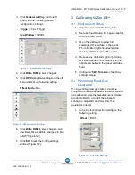
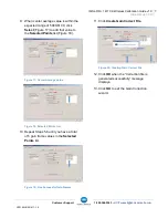
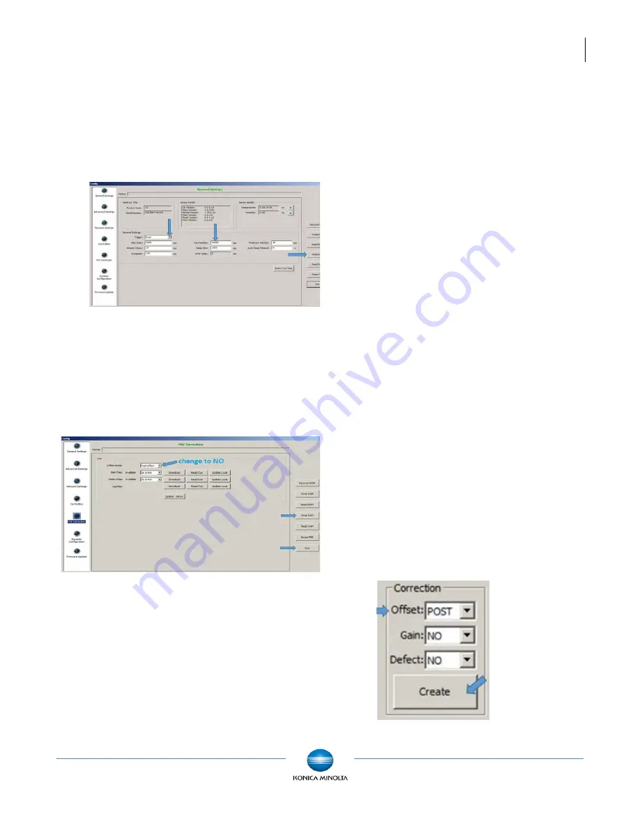
3. Click
General Settings
on the left
menu, set the following general
configuration settings.
Trigger
= Inner Trigger
Exp Window
= 30000
Figure 11: iDemo General Settings
4. Click
Write RAM
to save changes.
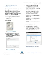
5. Click
HW Correction
settings on the left
menu and set the following setting.
Offset Mode
= No
Figure 12: HW Correction Settings
6. Click
Write RAM
to save changes. Gain
and Defect Map settings changes to “Do
in SW” (Figure 12).
7. Click
Exit
to exit the Config settings
window (Figure 12).
3 Calibrating ViZion DR+
3.1 Environment Setup
1. Align the panel with the X-ray tube.
2. Set tube head Source to Image-receptor
Distance (SID) to
60”
.
3. Open the collimator to allow full
coverage of the surface of the panel.
The collimator light should extend an
inch beyond the edges of the panel.
4. Remove any anti-static grid or grid-cap.
Make sure panel is out of bucky and no
objects are between the panel and tube
head.
5. Configure
70 kV 5.4 mAs
on the X-ray
control console.
3.2 Performing Panel Gain
Calibration
If using an integrated generator, it must be
configured to make exposures in Direct Mode to
run calibration. Use the manufacturer software
parallel to iDemo to control the generator
settings, or adjust kV and mAs from the
generator console.
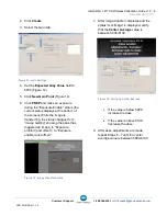
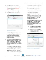
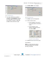
1. In the Correction section, configure the
following setting.
Offset
= POST
Figure 13: Correction Settings


