Page GB-16 Commissioning
– HU/CZ/SK/NL/SI/IS/HR/BA – PVC hose
according to EN 16436-1 2014 class 2
ID8 × 3.5 mm PVC hose with 2 hose
clamps L = 0.8 m
– DK – rubber hose according to EN
16436-1 2014 class 2 ID10.5 × 5 mm rub-
ber hose with 2 hose clamps L = 0.8 m
– ES/BG – PVC hose according to EN
16436-1 2014 class 2 ID10.5 × 5 mm
PVC hose with 2 hose clamps L = 0.8 m
– NO/FI – rubber hose according to EN
16436-1 2014 class 2 ID10 × 5 mm rub-
ber hose with 2 hose clamps L = 0.8 m
– TR/EE – PVC hose according to EN
16436-1 2014 class 2 ID10 × 5 mm PVC
hose with 2 hose clamps L = 0.8 m
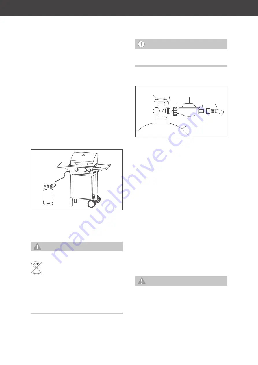
Location of gas tank
• Place the gas tank on flat and level
ground near the barbecue, never in the
cupboard under the appliance. Be careful
not to damage the hose in the process.
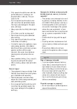
WARNING!
Explosion hazard!
The gas tank must not be placed inside the
barbecue!
Always keep access to the barbecue and
especially the gas tank free, keep escape
routes open.
NOTE
The gas hose must be a maximum of
1500 mm in length.
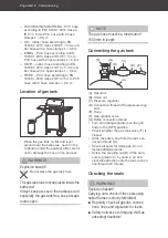
Connecting the gas tank
(A) Gas tank
(B) Union nut
(C) Pressure regulator
(D) Connection thread of the pressure regu-
lator
(E) Hose
(F) Gas cylinder valve
(G) Bottle connection thread
• Turn all rotating regulators on the grill
body to the [OFF] position.
• Check whether the gas tank valve (F) is
closed.
• Undo the safety cap from the tank con-
nection thread (G).
• Check all seals for damages. Do not
install additional seals.
• Screw the coupling nut (B) of the pres-
sure regulator (C) by hand in an anti-
clockwise direction onto the tank connec-
tion thread (left thread).
Checking the seals
WARNING!
Explosion hazard!
Carrying out a check of the seals using
naked flames is strictly forbidden!
■
Regularly check all gas line connec-
tions, lines and regulators for leaks.
■
Safety notices zum Umgang mit Gas
unbedingt beachten!
Do not place the gas tank here.
(F)
(A)
(B)
(G)
(C)
(D) (E)
Summary of Contents for 70415316
Page 11: ...Montage Seite DE 11 A x 12 6 7 9 12 6 8 A 10 A A 1 A x 8 5 5 A A 2 ...
Page 12: ...Seite DE 12 Montage 13 14 15 B C B x 2 C x 2 3 11 4 ...
Page 13: ...Montage Seite DE 13 A x 4 3 A A 5 16 4 A x 10 A A A A 6 ...
Page 15: ...Montage Seite DE 15 1 18 9 10 ...
Page 25: ...Pflege und Wartung Seite DE 25 3 4 5 ...
Page 35: ...Service Seite DE 35 ...
Page 36: ......
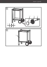
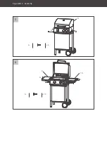
Page 46: ...Page GB 10 Assembly A x 12 6 7 9 12 6 8 A 10 A A 1 A x 8 5 5 A A 2 ...
Page 47: ...Assembly page GB 11 13 14 15 B C B x 2 C x 2 3 11 4 ...
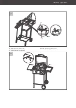
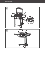
Page 48: ...Page GB 12 Assembly A x 4 3 A A 5 16 4 A x 10 A A A A 6 ...
Page 50: ...Page GB 14 Assembly 1 18 9 10 ...
Page 69: ...Service page GB 33 ...
Page 70: ......

