KÖNIG & MEYER
GmbH & Co. KG
Kiesweg 2, 97877 Wertheim, www.k-m.de
11912-000-55 / 11913-000-55 Rev.09 / Rev.07 03-79-242-00 10/20
SETUP INSTRUCTIONS
11912/11913
Orchestra music stand
INTENDED USE
Practical and uncomplicated orchestra music stand,
with special suitability for schools and orchestra
CHARACTERISTICS & SKILLS
- max. load capacity 2.8 kg
- Height adjustment: infinitely variable and without clamping
-
elements, simply by moving the tube combination
- Infinitely tiltable music stand top
- Integrated, impact sound absorbing parquet protectors
- Space-saving stackable - spacing only 70 mm - thanks to
-
special foot design
- Optional available: Trolley 11935 for transport and storage of
-
up to 12 orchestra music stands
- Height of the support: 740 -1280 mm; music stand top: 500 x 320 mm
SAFETY INSTRUCTIONS
Thank you very much for choosing this product. Please read and follow these
instructions carefully. They inform you about all important steps regarding
assembly and handling. We recommend that you keep them for future reference.
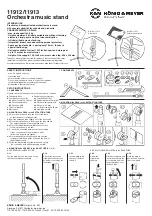
1. COMPONENTS
Visually check that all parts are present and in good condition.
a
Tripod with base
e
Desk mount accessories:
b
Foot mount accessories:
e
e.1
Joint half shell (2x)
b
b.1
Allen screw M5 x 16 mm
e
e.2
Rubber washer ø 30 mm (2x)
b
b.2
Threaded plate M5
e
e.3
Washer with square hole
b
b.3
Allen key SW4
e
e.4
Washer ø 8,5 mm
c
Tube combination
e
e.5
Locking screw M8 x 50 mm
d
Music desk
e
e.6
Clamping nut M8
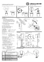
2. MOUNTING the DESK to the EXTRACTION TUBE
2.1
Place the music desk
d
on the floor or the table
2.1
so that the back is facing upwards.
2.2
Pull the extension tube slightly out of the base tube.
2.3
Place the joint half-shells
e.1
around the tube end
c.2
.
2.3
The spigots engage in the respective holes.
2.4
Press the rubber washers
e.2
into the recesses
2.4
of the joint half-shells
e.1
and…
2.5
…push this ensemble between the two retaining
2.5
straps on the back of the music desk until
2.5
the holes in all parts are aligned.
2.6
Place the washer with square hole
e.3
over the
2.6
locking screw
e.5
and guide it through the bore of
2.6
the holding brackets
2.7
Slide the washer
e.4
over the thread and secure
2.7
the connection with an M8 clamping nut
e.6
.
3. MOUNTING the SOCKET to the BASE TUBE (3.1 - 3.4)
3.1
PREPARING the BASE TUBE
3.2
Place THREADED PLATES in the BASE TUBE
- max. 2.8 kg load capacity
- center the load
- ensure that the surface is suitable and level
- Due to the moving parts, there is a risk of entrapment:
-
careful handling during assembly, operation and
-
dismantling is therefore essential.
3.1.1
Lay the plate flat on a table and set up
the tube combination vertically
3.1.2
Pull out the base tube
slightly until the slots are
no longer covered by the
inner tube
3.2.1
Insert plate
b.2
into
the slot of the base
tube
c.1
3.2.2
Screw
b.1
slightly into
the plate
3.2.3
Lift the screw head and
insert the plate into the
slot opposite until it no
longer protrudes over
the base tube
3.2.4
Hold the plate in
position and unscrew
the screw again
1. COMPONENTS
Art.-Nr.: 11912
Steel desk
Art.-Nr.: 11913
Polycarbonat desk
2. MOUNTING the DESK to the EXTRACTION TUBE


