Material
Base plate:
steel, powder-coated, basalt grey
Extension arm and support plate:
aluminium, powder-coated, basalt grey
Toothing discs :
zinc die-cast, powder-coated, black
Screws, washers:
steel, galvanised
Caps, handles, burls:
PE, PA, PUR, black
Load
max. 8 kg centered load
Dimensions
base plate: W x D: 303 x 284 mm
Support plate: W x D: 303 x 284 mm
Height: 65-265 mm
Cardboard
inside: 301 x 310 x 89 mm
Weight
2.9 kg
KÖNIG & MEYER
GmbH & Co. KG
Kiesweg 2, 97877 Wertheim, www.k-m.de
12195-000-87 Rev.2a 03-80-423-00 9/20
TECHNICAL DATA
MAINTENANCE, CLEANING
- Carry out care and maintenance work always in
-
unloaded condition.
-
At the same time pay attention and avoid potential
-
hazards such as e.g.: - jamming, - bumping, - tipping
- For routine care use a slightly damp cloth and a
-
non-abrasive cleaning agent
USER INSTRUCTIONS
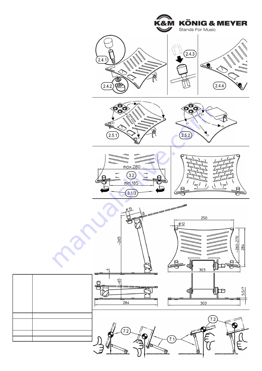
3. PLACING THE STOPS
3.1
Loosen wing nuts
b.1
...
3.2
...and shift the stop bolt as required
3.3
Retighten wing nuts
5. VENTILATION SLIT
The twelve slit in the support plate provide a
better ventilation for the placed equipment.
5. DIMENSIONS
6. ADJUSTING the INCLINATION
see chapter
2.3
SETUP and READJUSTMENT
7. SAFETY of SETTING
The stability of the stand and load depends on the:
7.1
Angle of inclination of the mounting plate, as well as
from the
7.2
position of the CG of load, which should be located
7.2
within the base plate of the stand.
7.2
NOTE!
7.2
First of all, always check carefully if the stand tends
7.2
to tilt after the load has been added.
7.2
Should this be the case, please select tip-proof setting.
FAULT-FINDING (F) and REPAIR (R)
F: Installation wobbles
F:
B: Check the surface (level and weight-bearing)
F:
B: Does the toothing of the locking discs interlock
F:
B:
properly without play?
F:
B: Are the rubber burls
c
under the foot plate
a.1
F:
B:
complete and correctly positioned?
F:
B: Are the screw connections tight?
F: The equipment doesn´t fit properly or wobbles
F:
B: Are the stop bolts
b
correctly positioned?
F:
B: Are the rubber burls
c
on the support plate
a.3
F:
B:
complete and correctly positioned?
2.4 STOPS
(
b.1-4
from the accessories bag)
2.4.1
Slide the stop bolt
b.3
from above through
2.4.1
one of the two lower slits of the support plate.
2.4.1
The lateral flattening of the bolts serves as
2.4.1
an anti-twisting device and must immerse
2.4.1
in the slit.
2.4.2
Screw wing nut
b.1
and washer
b.2
from
2.4.2
below to the stop bold
2.4.3
Press rubber cap
b.4
onto the bolt
2.4.4
Now mount the second stop
b
on the
2.4.4
other slit.
2.5 RUBBER BURLS
(
c
from the accessories bag)
2.5.1
Support plate: Affix four rubber burls (= 1 stripe),
2.5.1
whereby the exact spacing depends on the
2.5.1
equipment dimensions.
2.5.2
Base plate upper side: affix the last four rubber
2.5.2
burls or store for later use.
2.4 STOPS
2.5 RUBBER BURLS
3. PLACING THE STOPS
5. DIMENSIONS
5. VENTILATION SLIT
7. SAFETY of SETTING


