18807 Universal holder
INTENDED USE
- Retaining bracket for accessories attachment* to the
-
table-style keyboard stands »Omega« (18810, 18820) and
-
table-style keyboard stands (18950, 18953)
FEATURES & CAPABILITIES
- Stepless adjustable in height, distance and orientation (360°)
- It is attached to one of the legs of the keyboard stand
- Connection thread 3/8" or 5/8" (adapter); weight 1.61 kg
* Accessories: Music holder (18805), Adapter for screens (19685),
*
iPad stand holder (e.g. 19712), Tablet PC stand holder (19742, 19790, 19795)
*
Boom arms (e.g. 211), Goosenecks (e.g. 223)
SAFETY INSTRUCTIONS
- Perform visual inspection: damaged components must not be used
-
except after a professional repair or replacement.
- Generally, ensure that the screw connections are tight and correct.
- Observe assembly instructions, especially the correct use of the compen-
-
sation adapter
d
for the table-style keyboard stands 18950 and 18953.
- The clamping angle
c
may only be mounted with slots facing downwards.
- When changing the settings (height, direction, distance) always ensure
that the load is safe or if necessary, remove the load before.
- Please observe the safety instructions of the used keyboard stand.
ASSEMBLY INSTRUCTIONS
1. APPLICATION AREA
1.1
/
1.2
Table-style keyboard stands »Omega« 18810/18820 - WITHOUT
1.1
/
1.2
compensation adapter
d
1.3
/
1.4
Table-style keyboard stand 18950/18953 - WITH compensation adapter
d
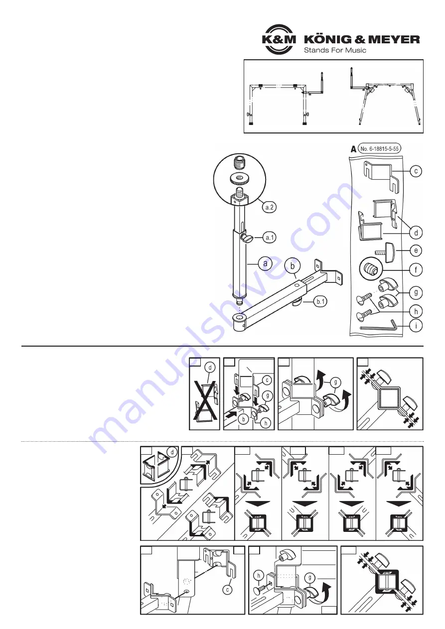
2. COMPONENTS
Please make a visual inspection, whether all parts are present and if so,
whether they are recognisably in order, especially the screw connections.
a
Stand/extension tube +
a.1
Clamping nut M6 for height adjustment
+
a.2
Connection thread 3/8", Knurled disc,
+
a.2
Reduction 5/8"
b
Boom/adjustment tube +
b.1
Clamping nut M6 for distance setting
ACCESSORIES BAG
A
(6-18815-5-55)
f
Set screw M6 x 8 mm, SW3
c
Clamping bracket with slots
g
2x Clamping nut M6, 33 mm wide
d
2x Compensation adapter for 18950/53
h
2x Carriage bolt M6 x 20 mm
e
Clamping screw M6 x 17 mm
i
Allen key SW3
3. MOUNTING ON THE KEYBOARD STAND
Mounting on the Table-style keyboard stand
»Omega« 18810 and 18820
The universal holder can be attached on each lateral standtube.
3.1
The compensation adapters
d
are not required: please sort them out.
3.2
Lock screws M6 x 20 mm
h
through the square holes of the boom/
3.2
adjustment tube
b
and slightly screw on both clamping nuts
g
.
3.2
Hold the angle of the boom tube
b
against the stand tube of the
3.2
»Omega« and slide the loose clamping bracket with slots
c
from
3.2
above over the screws.
3.3
Now tighten both clamping nuts
g
.
3.4
The clamping gap between the tightened angles
3.4
must have the same size.
Mounting on K&M Table-style keyboard
stands 18950 and 18953
We recommend two persons for the mounting.
All four table corners are suitable for mounting.
PREPARATION:
3.5
Both compensation adapters
d
are required:
3.5
please hold them ready.
3.6
Clip both compensation adapters
d
in the
3.6
respective angles as shown:
3.6
IMPORTANT: Due to the screw heads both
3.6
adapters have to be positioned accordingly,
3.6
see Fig.
3.6.1-4
(seen from above)
3.7
Clamping angle with slots
c
:
3.7
ALWAYS install with slots face down
ASSEMBLY:
3.8
Place the prepared angles on the chosen
3.8
leg of the folding table (see
3.6
- clear
3.8
compensation adapters
d
.
3.9
Slide both carriage bolts
h
first through the
3.9
square holes of the bracket on the boom/
3.9
adjustment tube
b
and then through the slots
3.9
of the clamping angle
c
.
3.10
Fit and tighten the clamping nuts
g
.
3.11
The clamping gap between the tightened
3.11
clamping angles should both have the
3.11
same size.
Thank you for choosing this product. Please read and follow carefully the instructions. They
inform you about all the important steps regarding set-up and handling. We recommend to
keep the instruction for future reference.
1.1 - K&M 18810
1.1
-
»Omega«
1.2 - K&M 18820
1.2
-
»Omega Pro«
18807
Universal
holder
1.3 - K&M 18950
1.1
-
Key.-Klapptisch
1.4 - K&M 18953
1.2
-
Stage-Klapptisch
3.1
3.5
3.8
3.7
3.9
3.11
3.10
3.6
3.6.1
3.6.2
3.6.3
3.6.4
3.2
3.3
3.4
1. APPLICATION AREA
2. COMPONENTS


