background image

Assembly


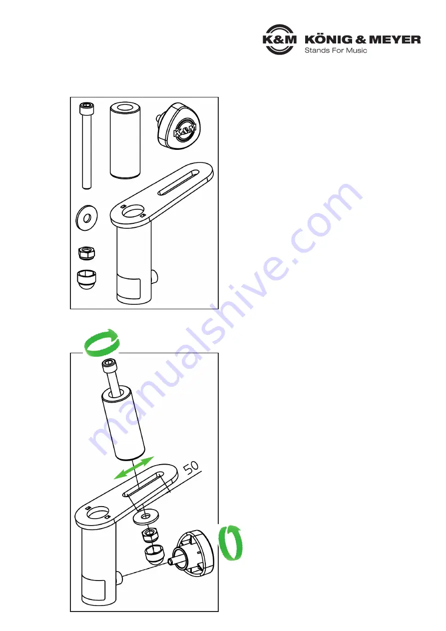
To assemble the speaker tilt connector, proceed as follows: 


1.) Unpack and check item for damage and completeness

● Holder 
● Mounting bolt 
● Clamping screw 
● Cylinder head screw M10 x 95 mm, washer, 
 

 nut M10 and protective cap

2.) Assembly of mounting bolt and clamping screw

Guide the cylinder head screw through the 
mounting bolt. 
Screw on the washer and nut from below. 
Using a suitable tool, tighten the screw connec-
tion and put the protective cap on the nut. By 
adjusting the mounting bolt via the slotted hole, 
the center of gravity of the loudspeaker can be 
varied. 
 
      The clamping screw should be screwed  
       into the thread.

Summary of Contents for 19671

Page 1: ...schgefahr u Durch die erreichbare Höhe besteht Gefahr durch herabfallende Teile u Die Nutzungsinformation ist Bestandteil des Artikels und ist für dessen Lebensdauer aufzube u wahren bzw an jeden nachfolgenden Besitzer oder Benutzer weiterzugeben Gewährleistung Keine Gewährleistung wird übernommen für Schäden die entstanden sind durch u Nichtbeachtung der Nutzungsinformation u Ungeeignete oder nic...

Page 2: ...e 2 Montage von Befestigungsbolzen und Klemmschraube Zylinderkopfschraube durch Befestigungs bolzen führen Von unten die Unterlegscheibe und Mutter verschrauben Mit geeignetem Werkzeug die Schraubenverbindung anziehen und die Schutzkappe auf die Mutter stecken Durch das Verstellen des Befestigungsbolzens über das Langloch kann der Schwerpunkt der Laut sprecherbox variiert werden Die Klemmschraube ...

Page 3: ...steller nicht weiter benutzen u Instandhaltungsarbeiten dürfen nur durchgeführt werden wenn Sie die erforderlichen Kennt u nisse hierfür besitzen Bei fehlenden Teilen kontaktieren Sie den Hersteller über www k m de u Hier gelangen Sie anhand der Artikelnummer die Sie auf dem Typenschild finden zu einem u entsprechenden Ersatzteilblatt Über dieses können Sie die fehlenden oder defekten Teile u Nach...

Page 4: ...06 150 E Mail contact k m de Web www k m de 19671 000 55 Rev 04 03 80 077 00 2 21 Störung Ursache Prüfen Behebung Boxenschrägsteller lässt sich nicht auf Stativ stecken Stativrohr überprüfen es muss einen Durchmesser von 35 mm haben Klemmschraube am Boxenschrägsteller weiter lösen diese darf nicht in das Innere des Aufnahmerohres ragen Boxenschrägsteller passt nicht in Lautsprecheraufnahme Lautspr...

Page 5: ...sk of falling parts due to attainable height u The usage information s are part of the product and must be kept for its service life or passed u on to any subsequent owner or user Warranty No warranty is given for damage caused by u Non observance of the usage information u Unsuitable or improper use u Incorrect installation or commissioning by the buyer or third parties u Natural wear and tear u ...

Page 6: ... protective cap 2 Assembly of mounting bolt and clamping screw Guide the cylinder head screw through the mounting bolt Screw on the washer and nut from below Using a suitable tool tighten the screw connec tion and put the protective cap on the nut By adjusting the mounting bolt via the slotted hole the center of gravity of the loudspeaker can be varied The clamping screw should be screwed into the...

Page 7: ... any damage that occurs and stop using the tilt connector u Maintenance work may only be carried out if you have the necessary knowledge If any parts u are missing contact the manufacturer at www k m de Here you can find a corresponding u spare parts list by entering the article number on the type label Use this page to reorder u missing or damaged components Place the speaker tilt connector on th...

Page 8: ...00 55 Rev 04 03 80 077 00 2 21 Fault cause Check Remedy Speaker tilt connector cannot be inserted on stand Check the stand tube it must have a diameter of 35 mm Loosen the clamping screw on the speaker tilt connector it should not protrude into the inside of the support tube Speaker tilt connector does not fit into loudspeaker holder The loudspeaker mount must have a diameter of at least 35 mm Lou...

Reviews: