background image

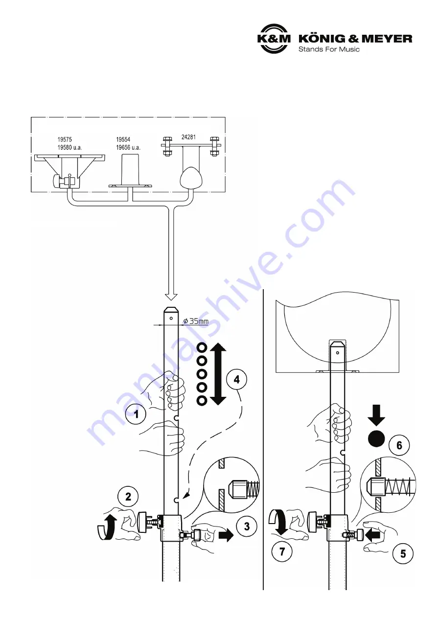
PLACEMENT and EXTENSION of the SATELLITE BOX

CHECK, MAINTENANCE, CLEANING

MOVING THE BOX

- Careful use of the stand maintains the use of the 

-

telescope and the load bearing functionality of the 

-

installation, as well as the safety of the installation.

- Perform workstation maintenance only without the 

-

weight on the support arms and watch for eventual 

-

risks (pinched fingers, impact, the rod falls over).

- To care for the product use a damp cloth and a 

-

non-abrasive cleaning agent.

FAULT FINDING (F) and SOLUTION (S)
F: Installation is not stable:

F: 

S: Ensure that the surface is even.

F: 

S: Check the relationship between the subwoofer 

F: S:

and satellite.

F: 

S: Tighten clamping screw 

7

.

F: 

S: Use Adapter Ring K&M 85890 

3.1

F: The extension tube is loose i.e. retracts when the 

F: 

speakers are attached:

F: 

S: Tighten the clamping screw 

7

.

F: 

S: Check locking pin 

5

to see if it is clicked into place.

ATTENTION!
The pneumatic spring is a great help in handling heavier weights. But the follo-
wing applies: do not underestimate the weight of the loudspeakers (max 35 kg)!
- The placement, extension and retraction of the loudspeakers must be 

-

performed by physically fit technicians. 

- Firmly grasp the distance rod when adjusting the height to the desired position 

-

and lock in the locking pin.

- NEW: the distance rod end is in the form of a peg, the so-called placement help,

which makes it much easier to place the loudspeaker onto the rod.

Technicians:
FP - First Person: operates the distance rod with the box

SP - Second Person: operates the clamping bracket's 
clamping screw and locking pin

Sequence when extending the rod:

FP - 

1

holds the distance rod

SP - 

2

loosens the clamp screw and holds it

SP -

3

pulls the locking knob until the locking pin 

SP -

3

is no longer in the locked position

FP - 

4

extends the (pneumatically supported) 

FP - 

4

distance rod with the box to the desired 

FP - 

4

approx. height;

FP - 

4

NOTE:

FP - 

4

To find the pin hole easily the locking pin 

FP - 

4

should be placed just above the hole

SP - 

5

lets go of the locking knob, (so that the pin 

SP - 

5

can click into the distance rod)

FP - 

6

slowly lowers the distance rod so that the 

FP - 

6

locking pin locks into the hole

SP - 

7

tightens the clamping screw 

SP - 

7

(manual strength is enough)

RETRACTING THE WEIGHT

When retracting the weight the 
reverse order applies.

NOTE:
- The locking pin 

3

can be unlocked by 

-

pulling and turning the handle 90°. This 

-

makes it  easier to retract the box, 

-

especially, if this is done by one person. 

- To ensure that the distance rod with the weight   

-

of the box is retracted slowly the friction of the 

-

clamping must be reduced delicately. To accomplish 

-

this loosen the clamping screw 

2

-

carefully.

- Should the box weigh 17 kg or less,  

-

the distance rod will have to be 

-

retracted with a little more 

-

power due to the pneumatic 

-

spring.

Application Examples (not included with the delivery) - Internal ø 35.5 mm

Summary of Contents for 21356

Page 1: ...rstutzen und der b Lautsprecherbuchse welches je nach Fabrikat leicht b unterschiedlich ausfallen kann Ein gewisses Spiel muss sein b um eine dauerhafte Gängigkeit zu gewährleisten Ggf den b Adapterring 85890 einsetzen siehe 3 c SICHERHEIT WÄHREND DES BETRIEBES c Stange zentrisch belasten c außermittige Lasten beeinträchtigen die Standfestigkeit c Unbefugte von der Installation fern halten c Siche...

Page 2: ...steckhilfe die das Aufsetzen des Lautsprechers wesentlich erleichtert Beteiligte EP Erste Person bedient das Auszugrohr mit der Last ZP Zweite Person bedient Klemmschraube und Rastbolzen der Spannschelle Reihenfolge beim Ausfahren EP 1 hält Auszugrohr fest ZP 2 lockert Klemmschraube und hält diese fest ZP 3 zieht den Rastknopf bis sich der Rastbolzen ZP 3 nicht mehr im Eingriff befindet EP 4 führt...

Page 3: ... manufacturer can differ somewhat A little play is required to b ensure continued usability If needed use Adapter Ring b 85890 refer to 3 c SAFETY DURING OPERATION c Be sure the weight on the rod is centered if the weight is not c centered this has a negative affect on stability c Keep unauthorized individuals away from the installation c Ensure that the clamp screw 7 is tight and the locking pin ...

Page 4: ...o called placement help which makes it much easier to place the loudspeaker onto the rod Technicians FP First Person operates the distance rod with the box SP Second Person operates the clamping bracket s clamping screw and locking pin Sequence when extending the rod FP 1 holds the distance rod SP 2 loosens the clamp screw and holds it SP 3 pulls the locking knob until the locking pin SP 3 is no l...

Page 5: ...itschaft nicht aus sich selbst heraus sondern nur zusammen mit einer Basis Bodenplatte oder Subwoofer herstellen SICHERHEITSHINWEISE Die Installation muss ausreichend gegen die Gefahr des Kippens gewappnet sein Dies gilt als gegeben wenn die sie den Prüfkriterien der Stativnorm DIN56950 3 standhält Dort heißt es Die Installation ist a um 5 geneigt b vollständig ausgezogen c in ungünstigster Stellu...

Page 6: ...iesem Fall sind es max 35 kg B Die Standsicherheit Tragkraft wie viel kg kann es unter den örtlichen B Gegebenheiten tragen bevor es kippt kg Bestehen des 5 Kipptestes vor Ort B Achtung Die Sicherheit des Tests gewährleisten Der geringere der beiden Werte gilt Dieser entspricht fast immer der im 5 Kipptest festgestellten Maximallast jedoch nicht mehr als max 35 kg GEFAHRENZONE Das Distanzrohr kann...

Page 7: ...do not operate on their own but only together with a base base plate or subwoofer SAFETY INSTRUCTIONS The installation must be adequately protected against the risk of tipping This is considered to be the case if it meets the test criteria of the standard specification DIN56950 3 There it says The installation is a inclined by 5 b fully extended c positioned in the most unfavourable position align...

Page 8: ...y load bearing capacity how many kg can it carry under local conditions B before it tilts kg passing the 5 tilting test on site B Attention Ensure the safety of the test The lower of the two values applies This almost always corresponds to the maximum load determined in the 5 tipping test but not more than max 35 kg DANGER ZONE The distance tube can act like a big lever a Lateral forces can put a ...

Reviews: