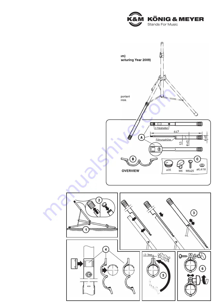
ASSEMBLY
SAFETY NOTES
- Only use the Leveling leg on the K&M stands listed here
-
(see Section
14
and
15
)
- Observe the safety notes of the stand being used
- Check the Leveling legs for damage before and after use. In case
-
of damage the product may not be used.
- The maximum central load is dependent on the stand, it may,
-
however, not exceed 35 kg.
- The Leveling leg is only to be used in the case of uneven surfaces
-
to ensure the upright level vertical position of the extension tube.
- The Leveling leg may not be used for finding a angled position of
-
the extension tube. Consider the increased danger of the stand
-
tipping over.
- not suitable for outdoors or moist rooms.
- routinely check the distances, tightness of the connections and
-
the condition of the system.
- Ensure that the system cannot be accessed by unauthorized
-
personnel, particularly as regards the connections/screws. If
-
needed, we recommend that the wing nut (manual operation)
-
included in the delivery be replaced with a nut that requires the
-
use of tools.
1
For optimal assembly, we recommend
1
setting up the stand, the tightening of
1
the clamp screws and to place it
1
lengthwise on the floor.
2
Remove the end-caps from the load-
2
bearing leg of the stand and replace
2
them with the cap.
3
Now push the tube (the long shaft
3
points outwards) as far as it will go on
3
the leg tube.
4
At the upper end of the shaft there are
4
three recesses. Place the clamping
4
bracket on the leg tube over the
4
recesses.
5
Now place the other side of the
5
clamping bracket around the leg until it
5
clicks into place, so that there are only
5
a few millimeters between the screw
5
holes.
6
Place the carriage bolt into the square
6
drill hole on both plates. Then place the
6
disk and tighten the wing nut.
PARTS - OVERVIEW
Conduct a visual inspection to ensure that all the parts are included and are in working order.
A
Tube with caps, Guide Sleeves, 3x Felt Strips
B
Clamping Bracket
C
Cap ø35 + Wing Nut M6 + Carriage Bolt M6 x25 + U-Disk ø6.4
Thank you for choosing this product. The instructions provide directions to all of the important
setup and handling steps. We recommend you keep these instructions for future reference.
21445 Leveling leg
for speaker stand
THIS PRODUCT ENSURES THAT
- many K&M stands are upright, sturdy and have secure hold on difficult surfaces
- the elegant leveler for uneven surfaces, stairs and slopes
... UND OFFERS MANY ADVANTAGES:
- levels height differences variably (depending on the stand up to 200 mm)
- retrofitted for many K&M stands with leg tubes - ø35 mm (since Manufacturing Year 2009)
- simple installation and operation
- with extension, anti-slip and anti-rotation protection
- very inconspicuous on the stand, whether it's being used or not
- can stay on the stand, even when the stand is not in use
-
(i.e. on level surface) or when the stand is collapsed
- Weight 0.7 kg
- NOTE: The weight bearing load of the installation is dependent
- NOTE:
on the loudspeaker stand, however a maximum of 35 kg.


