7
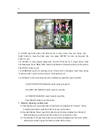
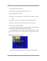
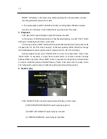
4). Forth channel / Right: push this button to see full screen display form channel 4.
While selecting menu items, push this button to move right the cursor.
5). Quad / Enter: push this button to see all pictures of 4 channels. While selecting menu
items, push this button to select the item.
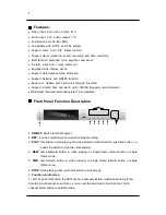
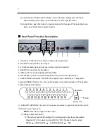
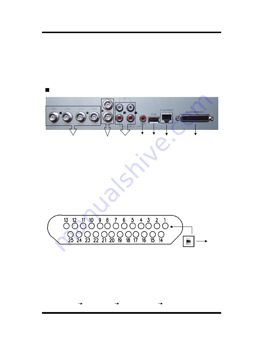
Rear Panel Function Description
1. Channel 1 to channel 4: for camera or other video signal input.
2. Two BNC connectors for video output.
3. 4 channels audio input, but just one can be output and recoded.
4. Red RCA connector for audio output.
5. USB port for record and update with Flash Disk.
6. Net interface: you can view the DVR picture from your PC through this port.
7. Alarm & RS485 connector: This DVR can support up to 4-alarm input, 1 relay alarm
output and RS485 function. You can use the adapter connecter to spread out. The detailed
setting described as followed.
①
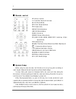
. SENSOR1~SENSOR4: One port of the sensor connected to signal input and the other to
GND. such as the figure upon.
NOTE:
there are two types of alarm input.
1. Voltage output (5V and 0V)
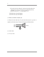
A: If the sensor output high voltage (5V) normally and output low voltage when
triggered (0V), then users must set DVR to “N.O”. Please follow the steps:
MENU SENSOR SET ALARM ENABLE ”NO”
1
2
3
4
5
6
7
Sensor CH1
GND
SENSOR1


