Product Description
JRex-IBOX – User’s Manual
15
Front Side with JFLEX-Sound1
2
2
5
4
6
8
7
1
1
3
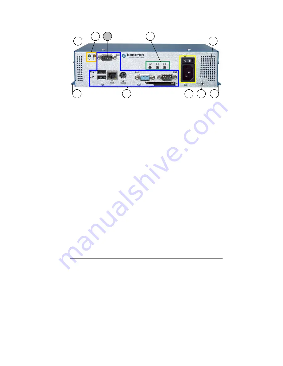
Fig. 5b: JRex-IBOX (shown as AC version with JFLEX-Sound1)
1
Bracket for wall mounting
2
Ventilation openings at the front
side
3
Interfaces of the SBC card with
CF slot and CF card holder
4
AC or DC power plug with the
corresponding On/Off switch
(depending on the ordered
system configuration)
5
M4 metric ground stud
6
LED indicators
7
Optional COM2 interface (TTL
level) (possible to be configured
only in system configuration with
JRex-CE-SBC card; for all others
system configurations the cut-out
for this interface connector is
covered)
8
Interfaces of the installed
expansion card on level1 (shown
with JFLEX-Sound1)
(if no expansion card is installed,
the cut-out for the interfaces are
covered)


