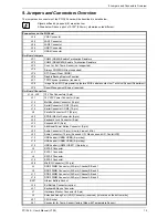
9. Jumpers and Connectors Overview
18
PCI-760 – User’s Manual (V1.00)
9.1.1.
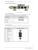
Connectors located on Slot Bracket
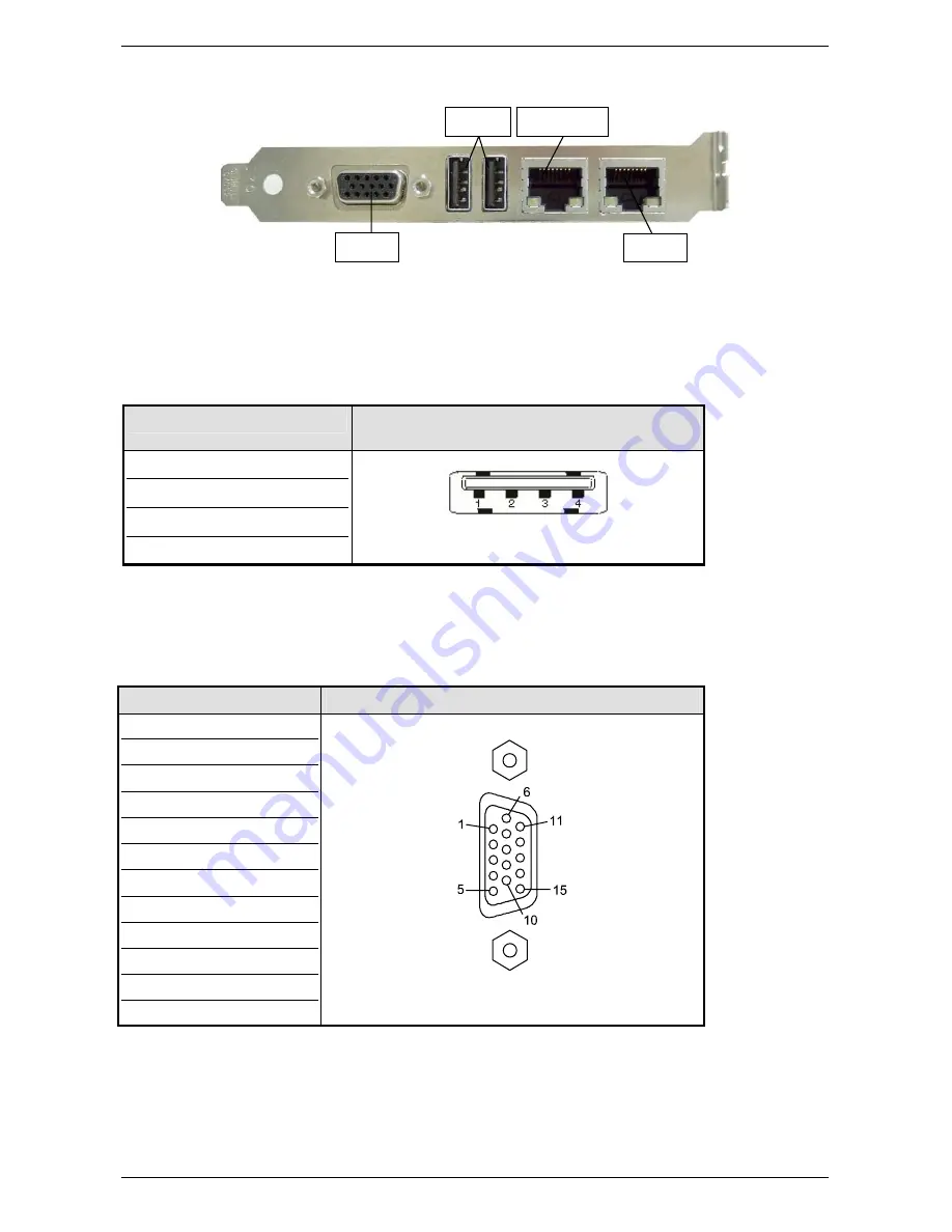
Fig. 5
Fig. 6: PCI-760 – Slot Interfaces
9.1.1.1.
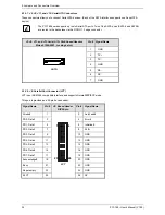
J29 and J30 USB Connectors
The slot bracket of the PCI-760 board provides two external USB 2.0/1.1 interfaces (USB6 and USB7). These
connectors allow connection of USB-compatible devices to the PCI-760 board (slot bracket).
Pin Signal
Name
4-pin USB Socket
Type A Version 2.0/1.1
1 VCC,
fused
2 Data-
3 Data+
4 GND
9.1.1.2.
J36: VGA Connector
An external (analog) monitor can be plugged into this interface which is provided as a 15-pin D-SUB socket.
Pin Signal
Name
15-pin D-SUB Socket (female)
1
Analog red output
2
Analog green output
3
Analog blue output
4 NC
5–8 GND
9
VCC, fused for DDC
10 GND
11
NC
12
SDA (DDC)
13 TTL
HSync
14 TTL
VSync
15 SCL
(DDC)
J36
2x USB
VGA
LAN2
LAN1

