background image

Summary of Contents for HPLC GRADIENT FORMER 425

Page 1: ...IA KONTRON INSTRUMENTS HPLC GRADIENT FORMER Instruction manual ...

Page 2: ...ng the mains supply 3 l 5 Installation 4 1 5 1 Pump modification 4 1 5 2 Installing the gradient former 5 1 5 3 Liquid connections 6 1 5 4 Electrical connection 6 1 5 5 Gas purge 7 1 5 6 Control Computer 7 2 INSTRUMENT DESCRIPTION General description 2 2 1 Specifications 2 2 2 Front panel 3 2 2 1 Controls 3 2 2 2 Status display 3 11 86 0 GENERAL INFORMATION l ...

Page 3: ...5 1 Time 9 3 5 2 Flow 9 3 5 3 A Step B Step C Step 10 3 5 4 Sync 10 3 5 5 Auxiliary 11 3 5 6 A programming example 11 3 5 7 General points 13 3 5 8 Leaving edit mode 14 3 6 Saving and loading files 14 3 7 Running files 14 3 8 System Status in file running mode 15 4 TROUBLE SHOOTING 4 1 Operation errors 2 4 2 Software error messages 3 5 MAINTENANCE 5 1 Routine maintenance 2 5 2 Spare parts 3 11 86 ...

Page 4: ...ing 2 1 2 Shipping list 2 1 3 Checking the serial number 3 1 4 Checking the mains supply 3 1 5 Installation 4 1 5 1 Pump modification 4 1 5 2 Installing the gradient former 5 1 5 3 Liquid connections 6 1 5 4 Electrical connection 6 1 5 5 Gas purge 7 1 5 6 Control Computer 7 11 86 l INSTALLATION l ...

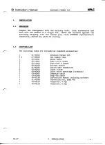
Page 5: ...LIST The following items are included äs Standard accessories 1 91 00553 Gradient Former 425 2 m 07 89023 Gas supply tube 1 55 65601 Mains cable 2 62 13001 Fuse 1 0 A 110V 2 62 13002 Fuse 0 63 A 220V 3 66 00452 Solvent bottle l 91 00560 Outlet tube connection 6 92 00910 Inlet filter l 92 00904 Inlet valve cartridge titanium l 93 00667 Computer cable l 93 00668 Pump 420 cable l 95 00196 Instruction...

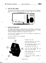
Page 6: ...lector see below situated at the rear of the Instrument Possible operating voltages 100 120 220 240 VAG The fuses on the voltage selector have to be changed to correspond with the mains supply voltage Frequency adjustment is not necessary Voltage selector Unplug mains cable Open the snap cover A using a screw driver at the top Pull marker wheel B and turn it to the required position Push B back in...

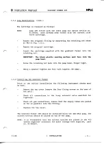
Page 7: ...hould be such that it is not exposed to dust or corrosive vapors The ambient temperature should be between 10 C and 35 C Allow at least 2 cm space around the System 1 5 1 Pump Modification The pump 420 must be modified äs described in the Installation instruc tion 84 00261 enclosed with the conversion kit The pump 420 must also be fitted with a medium pump head part no 91 00504 The connection betw...

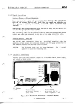
Page 8: ...mp head finger tight Using a Spanner tighten one füll turn approx 80 cmkp 1 5 2 Installing the Gradient Former Prior to the initial Installation the following Instrument checks must be made Remove the top cover remove the four fixing screws on the base of the unit Check all connections to the 3 way solenoid valve manifold for tightness Check all gas connections ensure that the supply tubes are pus...

Page 9: ...propriate purge button and a syringe attached to the end of the pump connection tube Gradient Former Pump 420 The outlet tube connection part no 91 00560 supplied1 with the gradient former should be connected between the 420 pump connection on the gradient former and the pump inlet fitting CAUTION The fittings must not be over tightened Use a second Spanner to hold the retaining nut 1 5 4 Electric...

Page 10: ...tem This can generally be avoided by purging the sol vents with inert gas prior to starting The gradient former is fitted with three independent regulating valves for controlling gas flow to the different solvent reservoirs A suitable inert gas connection must therefore be made to the gradient former Push the supply tube supplied with the gradient former firmly into the gas purge inlet connection ...

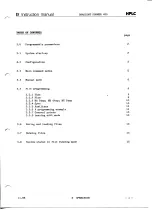
Page 11: ... manual GRADIENT FORMER 425 HPLC TABLE OF CONTENTS page 2 INSTRUMENT DESCRIPTION General description 2 2 1 Specifications 2 2 2 Front panel 3 2 2 1 Controls 3 2 2 2 Status display 3 11 86 2 INSTRUMENT DESCRIPTION l ...

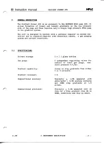
Page 12: ...plete with connection cables a gas purging System and solvent reservoirs 1 SPECIFICATIONS Solvent storage Gas purge Gradient capability Gradient increment Compositional accuracy Compositional precision 3 x 1 1 glass bottles 3 independent regulating valves for control of inert gas purge max inlet pressure 0 5 bar Linear or step gradients from either 2 or 3 solvents Typically H 1 5 measured with wat...

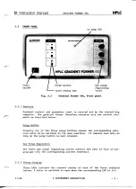
Page 13: ...äs described below Purge Button Pressing one of the three purge buttons causes the corresponding sole noid valve to be switched to its open position It remains open only äs long äs the purge button is kept pressed Gas Purge Regulation The three gas purge regulating valves control the rate of flow of pur ging gas into the corresponding solvent reservoir 2 2 2 Status Display Three LEDs indicate the ...

Page 14: ...Main command modes 5 3 4 Manual mode 6 3 5 File programming 9 3 5 1 Time 9 3 5 2 Flow 9 3 5 3 A Step B Step C Step 10 3 5 4 Sync 10 3 5 5 Auxiliary 11 3 5 6 A programming example 11 3 5 7 General points 13 3 5 8 Leaving edit mode 14 3 6 Saving and loading files 14 3 7 Running files 14 3 8 System status in file running mode 15 11 86 3 OPERATION l ...

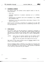
Page 15: ...nd pump 420 should be installed äs described in section l of this manual The Signal cable between gradient former and pump should be connected and the control cable to the gradient former connected between gradient former and COM1 on an IBM or IBM compatible PC CAUTION Before using the Software supplied with the gradient former you must make at least one back up copy for your own use Never work wi...

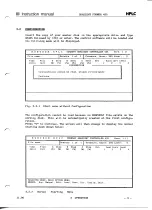
Page 16: ...figuration cannot be read please re configure Continue Fig 3 2 1 Start menu without Configuration The configuration cannot be read because no CONFHPLC file exists on the working disk This will be automatically created at the first configu ration Press C to continue The screen will then change to display the normal starting mask shown below K O N T R O N H P L C TERNARY GRADIENT CONTROLLER 425 Vers...

Page 17: ... on reproducibility and is primarily intended äs a correction factor for service use NOTE You should only therefore use the configuration module for definition of system pressure limits Set the required pressure limits by moving the cursor into the corres ponding field and entering the value required The value entered together with the ränge of permitted entries is shown on the last line in all ca...

Page 18: ...ally entered instructions EDIT is used to create or modify program files LOAD is used to load a previously created program file from disk SAVE is used to störe a previously created or modified file on disk DIR gives a directory listing of all program PRG type files stored on the working disk CONFIG selects the configuration menu QUIT returns you to MS DOS Selection of any command is made by enteri...

Page 19: ...Stop flow Interrupt Duration 0 9999 min 0 0 Fig 3 4 1 Manual Operation Menu All entries made in manual Operation are entered on the bottom line of the window The top line of this window is the status line and displays the current values for the various parameter e g the duration field always shows the elapsed time since the last instruction or the last set value of duration if the gradient has bee...

Page 20: ...nstruction The Status line will change to display a flow of 1 0 80 A and 20 B Example 2 Manual Mode Operation Using example l äs starting conditions and assuming you wish to run a linear gradient from 0 C to 80 C with a constant 20 B component in a time of 10 minutes Move the Cursor if necessary to duration Enter a time of 10 minutes press RETURN Press RETURN to enter the default value of l for th...

Page 21: ...ing times and then press E to execute these instruc tions even if a gradient is running Stop flow Pressing S will set the pump flow to 0 Stop flow is then replaced by Continue and you must press C to restart the flow at the originally set value The time will continue to run internally Gradient conditions at the time of restarting will be the same äs if the flow had not been stopped Interrupt Press...

Page 22: ...tep B Step C Step Syn Auxiliary sec 1 2 3 4 SELECTED MODE EDIT COMMANDS ESC Auxl On 0 999 sec 0 t Clear screen Delete line Sort Aux only Fig 3 5 1 Edit Mode Menu A program file consists of a set of instructions with a corresponding execution time for each instruction The significance of the various columns is described below 3 5 1 Time This is the execution time for the instruction set contained o...

Page 23: ... gradient over a period of 5 min 7 2 between 25 B and 75 B will be generated From this example it can be seen that entries for the end values of a linear gradient must be made in the A B and C columns respectively The start value for a linear gradient can however be either a ABC or a Step ABC value In cases where a step value is given this will always be treated äs the start value for a linear gra...

Page 24: ...d Aux l programmed for l second Switches on and starts the autosampler routine The autosampler then proceeds until the sample is in the sample loop and then the remote continue contact is closed The gradient former now waits until the next suction phase start and transmits a continue Signal to the master Computer The hold is then released The Controller goes immediately to the next line where Aux ...

Page 25: ...hin the GF425 Software Note that there are effectively 2 corners for each solvent at 9 minutes due to the step required this results in 6 corner points in total which are realized using the step instruction K O N T R O N H P L C TERNARY GRADIENT CONTROLLER 425 Vers 1 11 File nome EXAMPLE Repeats l of Pressure Upper 200 Lower Time min 0 0 2 0 2 1 7 0 9 0 10 0 Flow ml 1 0 1 0 1 0 l 0 1 0 A Step m 10...

Page 26: ... can be carried out easily äs shown above at 0 minutes The GF425 will immediately set the System to run in the above example at 25 A 25 B and 50 C Note that the 100 A entry is only necessary because the values in the linear entry column must total 100 The System will in this case never operate at 100 A Maintenance of isocratic composition over longer periods in a program file e g above between 7 a...

Page 27: ...th the save instruction already exist a prompt will be given before the existing file is overwritten To over write the existing file enter Y if you do not wish to overwrite then enter N and a new file name A stored file can be reloaded using the load command Press L and then enter the file name of the file required and press RETURN NOTE Pressing L also causes a directory of existing PRG files to b...

Page 28: ...ne of the main menu displays three important parameters for running of files FILE NAME defines the name of the currently running file REPEATS defines the current repeat status The total number of repeats required is shown on the right On the left the current repeat status is displayed X N PRESSURE defines the pressure limits configured and saved with the PRG file now being run The bottom line disp...

Page 29: ... Instruction manual GRADIENT FORMER 4 2 5 H P L C TABLE OF CONTENTS page 4 TROÜBLE SHOOTING 4 1 Operation errors 2 4 2 Software error messages 3 11 86 4 TROÜBLE SHOOTING l ...

Page 30: ...lack of reproducibility despite purging High purge gas consumption POSSIBLE SOLUTIONS System not adequately degassed Certain solvent combinations may require permanent purging with helium for reliable Operation if degassing can occur upon mixing System not adequately purged after standing Flush the System with suitable solvent combination to ensure that all connecting tubes are füll of degassed so...

Page 31: ...ND POSSIBLE SOLÜTION Run has been selected without loading a file or creating an instruction set in edit mode Entered value was not within the permitted ränge of values for that Parameter e g 101 for A Simply correct entry Incorrect entry of A B and C Parameter set Correct entry Incorrect entry of A B and C step parameters Correct entry 11 86 4 TROUBLE SHOOTING 3 ...

Page 32: ...13 Instruction manual GRADIENT FORMER 425 HPLC TABLE OF CONTENTS page 5 MAINTENANCE 5 1 Routine maintenance 2 5 2 Spare parts 3 11 86 5 MAINENTANCE l ...

Page 33: ...of the unit äs follows CAÜTION The unit nnist be disconnected from the raains power supply befbre removing the top cover Remove the four fixing screws at the base of the unit and remove the top cover Check the connections to the valve manifold for signs of leakage Tighten the tube connections if necessary Check that all connections to the gas regulating valves are firmly seated Replace the top cov...

Page 34: ... 71 00921 9 3 0 0 6 6 7 9 3 0 0 6 6 8 9 3 0 0 6 6 5 9 6 0 0 2 0 0 9 4 0 0 9 8 3 0 7 8 9 0 2 3 9 2 0 0 6 2 7 8 7 0 0 7 9 4 Description Outlet tube connection GF425 PÜ420 Inlet valve for Pump 420 Gable gradient former Computer Gable gradient former pump Solenoid valve assy Gas purge valve assy coniplete Gradient Controller printed circuitfaoard Tubing for gas purge Inlet filter Solvent feed tube 07 ...

Reviews: