background image

Preface

vii

RTM8020 User's Guide

Preface

How to Use This Guide

This user's guide is designed to be used as step-by-step instructions for installation and as a reference for 
operation, troubleshooting, and upgrades.

You can find the latest release of this User's Guide at:

http://www.kontron.com

 or at: 

ftp://ftp.kontron.ca/support/

For the circuits, descriptions and tables indicated, Kontron assumes no responsibility as far as patents or 
other rights of third parties are concerned.

The following is a summary of chapter contents:

• Chapter 1, Product Description

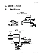
• Chapter 2, Board Features

• Chapter 3, Installing the board

• Appendix A, Connector Pinout

• Appendix B, Software Update

• Appendix C, Getting Help

Summary of Contents for AdvancedTCA RTM8020

Page 1: ...RTM8020 User s Guide Document Revision 1 1 May 2009...

Page 2: ...e owners All rights reserved Printed in Canada This user s guide contains information proprietary to Kontron Customers may reprint and use this user s guide in other publications Customers may alter t...

Page 3: ...ng Up the System ix Adapter Cables ix Storing Boards ix Regulatory Compliance Statements x Limited Warranty xi 1 Product Description 1 1 1 Product Overview 1 1 2 What s Included 1 1 3 Board Specificat...

Page 4: ...th LED2 14 2 8 3 Out of service LED1 14 3 Installing the Board 15 3 1 Board Hot Swap and Installation 15 3 1 1 Installing the RTM in the chassis 15 3 1 2 Removing the RTM from the chassis 15 A Connect...

Page 5: ...electronics service personnel should access the interior of the computer The power supplies produce high voltages and energy hazards which can cause bodily harm Use extreme caution when installing or...

Page 6: ...id possible damage to system boards wait five seconds after turning off the computer before removing a component removing a system board or disconnecting a peripheral device from the computer When you...

Page 7: ...ent s antistatic packing material until you are ready to install the component in a computer Just before unwrapping the antistatic packaging be sure you are at an ESD workstation or grounded This will...

Page 8: ...e of this User s Guide at http www kontron com or at ftp ftp kontron ca support For the circuits descriptions and tables indicated Kontron assumes no responsibility as far as patents or other rights o...

Page 9: ...following is an example of each type of advisory Use caution when servicing electrical components Disclaimer We have tried to identify all situations that may pose a warning or a caution condition in...

Page 10: ...ctors are properly connected Verify your boot devices If the system does not start properly try booting without any other I O peripherals attached including AMC adapters Make sure your system provides...

Page 11: ...an experience radio TV technician for help UL Certification This product bears the combined UL Recognized Component Mark for Canada and U S It indicates investigations to the UL Standard for Safety o...

Page 12: ...cost of purchase if appropriate In the event of repair refunding or replacement of any part the ownership of the removed or replaced parts reverts to Kontron and the remaining part of the original gua...

Page 13: ...ial port two 3Gbit s SAS links and integrates an onboard SAS drive for either additional functionality or extended customization by saving an AdvancedMC slot on the processing blade for other IO or pr...

Page 14: ...arm board temperature sensor power failure Mechanical 322 25 x 93 74 x 29 mm Power Requirements 25W maximum Environmental Temperature Operating 0 55 C 32 131 F with 30CFM airflow Storage and Transit 4...

Page 15: ...cture SAS1R10 Serial Attached SCSI 1 1 Revision 10 SAS 1 1 SFF 8470 T10 Technical Committee and SCSI Trade Association 1 5 Hot Swap Capability The RTM8020 supports Full Hot Swap capability as per PICM...

Page 16: ...10 SFF 8470 SAS signal integrity guarantee over a four meters cable 1 6 1 3 Serial Port Feature One 1 serial port available on the RTM face plate through one 1 RJ 45 connector RS 232 signals level at...

Page 17: ...the CPU SW there is a functional RTM blade present 1 6 1 6 2 Removing the RTM8020 from the slot The RTM_EJECT signal goes HIGH by opening the RTM lower ejector handle This indicates to the front blad...

Page 18: ...Board Features 6 RTM8020 User s Guide 2 Board Features 2 1 Block Diagram...

Page 19: ...S transfer rate Standardization of peripheral interfaces into a single format Backward compatible with USB 1 1 devices USB supports Plug and Play and hot swapping operations OS level These features al...

Page 20: ...located on the component side of the PCB in the lower part of the RTM8020 2 5 Serial Port The RTM8020 has one serial port available on the RTM face plate Serial port signals are coming from the front...

Page 21: ...that forward it to the ShMc ensure that post mortem logging information is available even if the power of the RTM is disabled The onboard DC voltages and temperature are monitored by the MMC microcon...

Page 22: ...prespective the RTM8020 management controller is set up as a satellite management controller SMC It does support sensor devices and use the IPMI static sensor population feature of IPMI v1 5 to merge...

Page 23: ...er or version number can be read through software FRU information in the RTM8020 includes data describing the RTM8020 board as per AMC 0 R1 0 specification requirements This information is retrieved b...

Page 24: ...ust be in synch Please always follow Kontron documentation for all your upgrades The recommended upgrade sequence must be FWUM first then MMC MMC Firmware upgrades can be done by using IPMITOOL from t...

Page 25: ...states are possible When the RTM latch is disengaged from the faceplate the hot swap switch embedded in the PCB will assert a HOT_SWAP_PB signal to the MMC and the MMC will send Module Handle Open ev...

Page 26: ...Management LED represents MMC communication over IPMB L when pulsing 2 8 2 RTM Health LED2 The green LED indicates that the RTM is working properly The amber LED indicates that the RTM is in fault 2...

Page 27: ...nstall the RTM 1 Remove the filler panel of the slot 2 Ensure the board is configured properly 3 Carefully align the PCB edges in the bottom and top card guide 4 Insert the board in the system until i...

Page 28: ...de A Connector Pinouts A 1 CONNECTORS AND HEADERS SUMMARY Connector Description P30 RTM Connector J2 USB 2 0 Connector J3 SAS Faceplate Connector J5 Serial Port Connector J7 POST Code Connector J10 SA...

Page 29: ...C N C N C N C N C N C 7 N C N C N C N C N C N C 8 N C N C N C N C N C N C 9 P0_TX P0_TX P0_RX P0_RX P1_TX P1_TX 10 P2_TX P2_TX P2_RX P2_RX P3_TX P3_TX Pin ROW G ROW H ROW AB ROW CD ROW EF ROW GH 1 RTM...

Page 30: ...Pin Signal S1 RX_0 G1 GND S2 RX_0 G2 GND S3 RX_1 G3 GND S4 RX_1 G4 GND S5 N C G5 GND S6 N C G6 GND S7 N C G7 GND S8 N C G8 GND S9 N C G9 GND S10 N C S11 N C MTG1 CGND_1 S12 N C MTG2 CGND_2 S13 TX_1 S1...

Page 31: ...2 Data 3 Clock 4 GND Pin Signal Pin Signal S1 GND P1 3 3V S2 PortA_TX P2 3 3V S3 PortA_TX P3 3 3V S4 GND P4 GND S5 PortA_RX P5 GND S6 PortA_RX P6 GND S7 GND P7 5V S8 GND P8 5V S9 PortB_TX P9 5V S10 Po...

Page 32: ...ate Procedure The IPMC Firmware update procedure is detailed in a ReadMe file included with the IPMC Firmware package as well as the update utility This package can be downloaded from our website http...

Page 33: ...2 Tel 49 0 8341 803 333 Fax 450 437 8053 Fax 49 0 8341 803 339 If you have any questions about Kontron our products or services visit our Web site at www kontron com You also can contact us by E mail...

Page 34: ...hnician will instruct you on the return procedure if the problem cannot be solved over the telephone 4Make sure you receive an RMA from our Technical Support before returning any merchandise Fax 1Make...

Page 35: ...voice s associated with the item s in question Ensure that the unit is properly packed Pack it in a rigid cardboard box Clearly write or mark the RMA number on the outside of the package you are retur...

Page 36: ...______ City __________________________ Province State _________________________ Country __________________________ Postal Zip Code _________________________ Phone Number __________________________ Ext...

Reviews: