
Board Features
11
X
Exceed critical threshold
*
Power On/Off
-
Power On
N
No change
2.7.2.1
IPMB-L Link Sensor
The RTM8020 has an IPMB-L links to communicate with the processor board and other devices in the
chassis chassis IPMB-0 bus. MMC monitors the bus for any link failure and sends the bus failure
event to the RTM upon the recovery occurs.
2.7.2.2
Module Hot Swap
The hot-swap event message conveys the current state of the module, the previous state and a
cause of the state change as can be determined by the MMC. Refer to AMC.0 R2.0 specifications for
further details on the module hot-swap state.
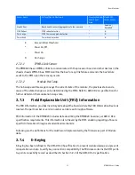
2.7.3
Field Replaceable Unit (FRU) Information
The FRU Information provides inventory data about the boards where the FRU Information Device is
located. The part number or version number can be read through software.
FRU information in the RTM8020 includes data describing the RTM8020 board as per AMC.0 R1.0
specification requirements. This information is retrieved by the RTM, enabling reporting of board-
specific information through a standardized mechanism.
Following are the definitions for the multirecord implemented by the firmware as part of Module
data.
2.7.4
E-Keying
E-Keying has been defined in the AMC.0 R1.0 Specification to prevent module damage and prevent
misoperation and also to verify bay connection compatibility. The FRU data contains the RTM point-
to-point connectivity record as described in Section 3.9.2 of the AMC.0 R1.0 specification.
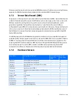
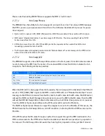
Health Error
Board health sensors (aggregation of other sensors)
*
Asserted /
Desserted
MMC Reboot
IPMC reboot detection
*
N
Ver change
IPMC firmware upgrade detection
*
N
Power Good
Power Good detection
*
N
Sensor Name
Voltage/Signals Monitored
Scanning Enabled
under Power
State
Health LED
(Green to Red)