Installing the Board
15
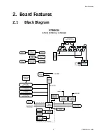
3. Installing the Board
3.1
Board Hot Swap and Installation
Because of the high-density pinout of the hard-metric connector, some precautions must be taken when
connecting or disconnecting a board to/from a backplane:
1 Rail guides must be installed on the enclosure to slide the board to the backplane.
2 Do not force the board if there is mechanical resistance while inserting the board.
3 Screw the frontplate to the enclosure to firmly attach the board to its enclosure.
4 Use extractor handles to disconnect and extract the board from its enclosure.
3.1.1
Installing the RTM in the chassis
To install the RTM:
1 Remove the filler panel of the slot.
2 Ensure the board is configured properly.
3 Carefully align the PCB edges in the bottom and top card guide.
4 Insert the board in the system until it makes contact with the CPU board.
5 Using both ejector handles, engage the board in the CPU board connectors until both ejectors are locked.
6 Fasten screws at the top and bottom of the faceplate.
3.1.2
Removing the RTM from the chassis
To remove the RTM:
1 Unscrew the top and the bottom screw of the faceplate.
2 Unlock the lower handle latch.
3 Wait until the blue LED is fully ON, this mean that the hot swap sequence is ready for board removal.
4 Use both ejectors to disengage the board from the CPU board.
5 Pull the board out of the chassis.
WARNING
Always use a grounding wrist wrap before installing or removing the board from a
chassis.


