background image

COMe-bKL6 – User Guide Rev.1.2 


www.kontron.com 


// 14 


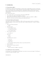
1.4.


COM Express® Functionality 

All Kontron COM Express® basic and compact modules contain two 220 pin connectors. Each connector has two rows 
called Row A & B on the primary connector and Row C & D on the secondary connector. COM Express® Computer-On-
Modules feature the following maximum amount of interfaces according to the PICMG module pinout type. 

Table 1: Pin Assignment of Type 6 and COMe-bKL6 

Feature 

Type 6 Pinout 

COMe-bKL6 Pinout 

HD Audio 

1x 

1x 

Gbit Ethernet 

1x 

1x 

Serial ATA 

4x 

4x 

PCI Express x 1 

8x  

8x  

PCI Express x16 (PEG) 

1x 

1x 

USB Client 

1x (optional) 

1x (optional) 

USB  

4x USB 3.0 (Incl. USB 2.0)  
+ 4x USB 2.0 

4x USB 3.0 (Incl. USB 2.0)   
+ 4x USB 2.0 

VGA 

1x 

1x optional DP to VGA converter 

LVDS (eDP) 

Dual Channel 

Dual Channel LVDS with option to 
overlay (eDP) 

DP++ (DP/HDMI/DVI) 

3x 

3x 

LPC 

1x 

1x 

External SMB 

1x 

1x 

External I2C 

1x 

1x 

GPIO 

8x 

8x 

SDIO shared w/GPIO 


UART (2-wire COM) 

2x 

2x 

FAN PWM out 

1x 

1x 

1.5.


COM Express® Benefits 

COM Express® defines a Computer-On-Module, or COM, with all the components necessary for a bootable host 
computer, packaged as a highly integrated computer. All Kontron COM Express® modules are very compact and 
feature a standardized form factor and a standardized connector layout that carry a specified set of signals. Each 
COM is based on the COM Express® specification. This standardization allows designers to create a single-system 
baseboard that can accept present and future COM Express® modules. 

The baseboard designer can optimize exactly how each of these functions implements physically. Designers can 
place connectors precisely where needed for the application, on a baseboard optimally designed to fit a system’s 
packaging. 

A single baseboard design can use a range of COM Express® modules with different sizes and pinouts. This flexibility 
differentiates products at various price and performance points and provides a built-in upgrade path when designing 
future-proof systems. The modularity of a COM Express® solution also ensures against obsolescence when computer 
technology evolves. A properly designed COM Express® baseboard can work with several successive generations of 
COM Express® modules. 

A COM Express® baseboard design has many advantages of a customized computer-board design and, additionally, 
delivers better obsolescence protection, heavily reduced engineering effort, and faster time to market.


Summary of Contents for COMe-bKL6

Page 1: ...USER GUIDE www kontron com 1 COMe bKL6 Doc User Guide Rev 1 2 Doc ID 1061 1954...

Page 2: ...COMe bKL6 User Guide Rev 1 2 www kontron com 2 This page has been intentionally left blank...

Page 3: ...be suitable for the specified use without further testing or modification Kontron expressly informs the user that this user guide only contains a general description of processes and instructions whic...

Page 4: ...s is entirely at your risk To minimize the risks associated with your products and applications you should provide adequate design and operating safeguards You are solely responsible for compliance wi...

Page 5: ...tion refer to the corporate offices contact information on the last page of this user guide or visit our website CONTACT US Customer Support Find Kontron contacts by visiting http www kontron com supp...

Page 6: ...cribed by the law may endanger your life health and or result in damage to your material ESD Sensitive Device This symbol and title inform that the electronic boards and their components are sensitive...

Page 7: ...before performing any work on this product Earth ground connection to vehicle s chassis or a central grounding point shall remain connected The earth ground cable shall be the last cable to be discon...

Page 8: ...oduct then re pack it in the same manner as it was delivered Special care is necessary when handling or unpacking the product See Special Handling and Unpacking Instruction Quality and Environmental M...

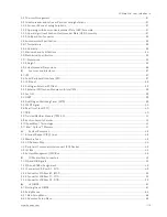
Page 9: ...2 1 1 Commercial Grade Modules 0 C to 60 C 15 2 1 2 Extended Temperature Grade Modules E1 25 C to 75 C 15 2 1 3 Industrial Temperature Grade Modules E2S 40 C to 85 C 16 2 2 Accessories 16 2 3 Functio...

Page 10: ...nal SPI Flash 38 3 2 3 External SPI flash on Modules with Intel ME 39 3 3 Fast I2C 39 3 4 UART 39 3 5 Dual Staged Watchdog Timer WTD 39 3 5 1 WDT Signal 40 3 6 Real Time Clock RTC 40 3 7 GPIO 40 3 8 T...

Page 11: ...e 12 Temperature Grade Specifications 33 Table 13 Humidity Specification 33 Table 14 Standards and Certification Compliance 34 Table 15 Supported BIOS Features 37 Table 16 SPI Boot Pin Configuration 3...

Page 12: ...sions 36 Figure 5 X1A and X1B COMe Interface Connectors 47 Figure 6 Main Setup Menu Initial Screens 63 Figure 7 Advanced Setup Menu Initial Screen 65 Figure 8 System Agent Configuration Menu Initial S...

Page 13: ...0 incl USB 2 0 4x USB 2 0 Support for both commercial and Industrial temperature grade environments 1 2 Product Naming Clarification COM Express defines a Computer On Module or COM with all the compon...

Page 14: ...a highly integrated computer All Kontron COM Express modules are very compact and feature a standardized form factor and a standardized connector layout that carry a specified set of signals Each COM...

Page 15: ...le with Intel Core i7 7820EQ 4x3 0GHz QM175 PCH GT2 2x DDR4 non ECC SO DIMM 38032 0000 29 5 COMe bKL6 i5 7440EQ QM175 COM Express basic pin out type 6 Computer on Module with Intel Core i5 7440EQ 4x2...

Page 16: ...ECC ECC SO DIMM Rapid Shutdown industrial temperature grade 38033 0000 29 3 COMe bKL6R E2S i3 7100E CM238 COM Express basic pin out type 6 Computer on Module with Intel Core i3 7100E 2x2 9 GHz CM238 P...

Page 17: ...Me bHL6 bBL6 bSL6 bKL6 passive w o HSP For all CPUs and commercial temperature grade usage to be mounted on HSP Part Number Mounting Description 38017 0000 00 5 COMe Mount KIT 5 mm 1 set Mounting Kit...

Page 18: ...MHz PC4 2400 SO DIMM 97017 1600 24 2 DDR4 2400 SODIMM 16 GB E2_COM DDR4 2400 16GB E2 260P 1200MHz PC4 2400 SODIMM Part Number Memory ECC validated reference types 97018 4096 24 0 DDR4 2400 SODIMM 4 GB...

Page 19: ...0 3 USB2 0 PWM FAN2 I2C SER0 SER1 eDP x2 USB 4 7 USB 2 0 PCIe 0 5 Intel 7th Generation Core Intel Xeon E3 v6 Family Kaby Lake H Series LID Sleep SPI BIOS Flash Connector Option Standard component GB L...

Page 20: ...le 8 Processor Specifications are compatible with the COMe bKL6 functional specification For more information on features supported by the COMe bKL6 see the relevant subheading in Chapter 2 3 Function...

Page 21: ...variants Intel CM238 Commercial temperature grades for all Core i3 Xeon E3 processor variants Intel CM238 Industrial temperature grades for all processor variants The following table lists the specifi...

Page 22: ...on DDI0 Optional VGA Display port to VGA converter DP2VGA on DDI3 2 3 5 2 Display Resolution The following table lists the maximum display resolutions at a set frequency and bit per pixel bpp for the...

Page 23: ...H High speed I O Port PCH I O Function Comment PCIE0 15 PCIe 9 Also serves as an Intel PCIe Storage Device 1 PCIE1 16 PCIe 10 PCIE2 17 PCIe 11 PCIE3 18 PCIe 12 PCIE4 7 PCIe 1 PCIE5 8 PCIe 2 PCIE6 9 PC...

Page 24: ...1 1 Lane 10 10 2 2 Lane 11 11 3 3 Lane 12 12 4 0 Linked with 0 1 2 Segment Bus Device Lane 13 13 5 1 Lane 14 14 6 2 Lane 15 15 7 3 The following table lists the PCI Express Graphics x16 PEG port bifu...

Page 25: ...SB2_6 USB6 USB2_7 USB7 USB2_8 2 3 10 SATA The SATA high speed storage interface supports four SATA Gen3 ports with transfer rates of up to 6 Gb s The following SATA ports are available at the followin...

Page 26: ...refer to the EMD Customer Section or contact Kontron Support 2 3 12 COMe High speed Serial Interfaces Overview The following table provides an overview of the COMe connector s PCH high speed serial i...

Page 27: ...rating System OS Windows 10 64 bit Linux 64 bit LiveCD VxWorks 7 x 64 bit 2 3 15 COMe Features The following table lists the supported COM Express features SPI Boot from an external SPI LPC Supported...

Page 28: ...Rise Time The input voltage rise time is 0 1 ms to 20 ms from input voltage 10 to nominal VCC To comply with the ATX specification there must be a smooth and continuous ramp of each DC input voltage...

Page 29: ...till occurring Once the reset is asserted it remains asserted for 5 ms to 6 ms regardless of whether the SYS_RESET input remains asserted or not SM Bus Alert SMB_ALERT Pin B15 With an external battery...

Page 30: ...on the module from S5 state press the power button or reconnect VCC Suspend Standby states are not supported in single supply mode The following table lists the single supply mode settings State PWRB...

Page 31: ...onditions Active or passive cooling solutions provided from Kontron for the COMe bKL6 are usually designed to cover the power and thermal dissipation for a commercial temperature range used in housing...

Page 32: ...n to the module use one of the following adaptor cables KAB HSP 200 mm PN 96079 0000 00 0 KAB HSP 40 mm PN 96079 0000 00 2 If the input voltage is below 13 V the maximum supply current to the on board...

Page 33: ...for the COMe bKL6 see Chapter 2 1 Module Variants Table 12 Temperature Grade Specifications Temperature Grades Operating Non operating Storage Commercial Grade 0 C to 60 C 30 C to 85 C Extended Grade...

Page 34: ...SD immunity IEC EN 61000 4 3 Radiated radio frequency electromagnetic field immunity IEC EN 61000 4 4 Electrical fast transient burst immunity IEC EN 61000 4 5 Surge immunity IEC EN 61000 4 6 Immunity...

Page 35: ...the height of the implemented cooling solution The height of the cooling solution is not specified in the COM Express specification The COM Express specification defines a module height of approximate...

Page 36: ...ide Rev 1 2 www kontron com 36 2 8 3 Heatspreader Dimensions The following figure shows the heatspreader s dimensions and location on the module Figure 4 Heatspreader Location and Dimensions All dimen...

Page 37: ...Kontron COM Express Computer on Modules imply BIOS support for the following external baseboard LPC Super I O controller features for the Winbond Nuvoton 83627DHG P Table 15 Supported BIOS Features 3...

Page 38: ...I plugged in on the system Depending on which SPI you would like to flash you will need to use the BIOS_DIS1 jumper located on the COM Express carrier To flash the carrier or module Flash chip 1 Conne...

Page 39: ...s on the same board The COMe bKL6 features an onboard I2C controller connected to the LPC Bus The I2C controller supports Multimaster transfers Clock stretching Collision detection Interruption on com...

Page 40: ...ss connector offers a signal that can be asserted when a watchdog timer has not been triggered within a set time The WDT signal is configurable to either of the two stages After reset the signal is au...

Page 41: ...embedded hardware security module and a software framework to provide full protection for your application The COMe bKL6 includes an integrated security module connected to USB2 port 9 supporting the...

Page 42: ...Intel Optane is available on the Rapid Storage capable PCIe Ports PCIE 0 3 and supports the x2 and x4 configuration options only Owing to the fact that the PCIE 0 3 are configured as four times x1 In...

Page 43: ...e following table specifies the usage of the address ranges within the memory area Table 20 Designated Memory Locations Address Range hex Size Project Usage 00000000 0009FBFF 639 KB Real mode memory 0...

Page 44: ...253 04E 04F 2nd SuperIO TPM etc TPM 060 064 KBD Interface Controller 8042 KBD Interface Controller 8042 061 063 065 067 NMI Controller NMI Controller 062 066 Embedded Microcontroller Not used 070 071...

Page 45: ...PLD control port CF8 PCI configuration address PCI configuration address CF9 Reset control Reset control CFC CFF PCI configuration data PCI configuration data Other PCI device I O addresses are alloca...

Page 46: ...write address for all devices The7 bit SMBus address shows the device address without Bit0 Table 23 SMBus Addresses 8 bit Address 7 bit Address Device Comment SMBus 5Ch 2Eh HWM NCT7802Y Do not use und...

Page 47: ...interface connectors X1A and X1B Figure 5 X1A and X1B COMe Interface Connectors 5 1 X1A and X1B Signals For description of the terms used within the pin assignment tables see the General Signals Descr...

Page 48: ...Resistor OA Output Analog PWR Power Connection OD Output Open Drain and Differential Pair To protect external power lines of peripheral devices make sure that the wires have the right diameter to with...

Page 49: ...l ATA transmit data pair 0 DP O A17 SATA0_TX A18 SUS_S4 Indicates system is in Suspend to Disk or deeper state O 3 3 PD 10 k A19 SATA0_RX Serial ATA receive data pair 0 DP I A20 SATA0_RX A21 GND Power...

Page 50: ...PU 10 k 3 3 V S0 A50 LPC_SERIRQ Serial interrupt request I OD 3 3 PU 8 2 k 3 3 V S0 A51 GND Power ground PWR GND A52 PCIE_TX5 PCI Express transmit lane 5 DP O A53 PCIE_TX5 A54 GPI0 General purpose inp...

Page 51: ...sserted A93 GPO0 General purpose output 0 O 3 3 PD 100 k A94 SPI_CLK Clock from module to carrier SPI O 3 3 PU 15 k to 40 k in PCH S5 All SPI signals tri stated with 20 K CPU internal weak pull up unt...

Page 52: ...6 SATA1_TX SATA 1 transmit data pair DP O B17 SATA1_TX B18 SUS_STAT Indicates imminent suspend operation used to notify LPC devices O 3 3 B19 SATA1_RX SATA 1 receive data pair DP I B20 SATA1_RX B21 GN...

Page 53: ...RX5 B54 GPO1 General purpose output 1 O 3 3 PD 100 K B55 PCIE_RX4 PCI Express receive lane 4 DP I B56 PCIE_RX4 B57 GPO2 General purpose output 2 O 3 3 PD 100 K B58 PCIE_RX3 PCI Express receive lane 3...

Page 54: ...or O 3 3 B95 VGA_DDC_CLK Display Data Channel DDC clock line I O 5 PU 2 4 K 3 3 V S0 B96 VGA_DCC_DATA Display Data Channel DDC data line I O 5 PU 2 4 K 3 3 V S0 B97 SPI_CS Chip select for carrier boar...

Page 55: ...I Express receive lane 6 DP I C20 PCIE_RX6 C21 GND Power Ground PWR GND C22 PCIE_RX7 PCI Express receive lane 7 DP I C23 PCIE_RX7 C24 DDI1_HPD DDI1 Hotplug Detect I 3 3 PD 100 K C25 DDI1_PAIR4 DDI1 da...

Page 56: ...use NC C64 RSVD C65 PEG_RX4 PCI Express Graphics PEG receive lane 4 DP I C66 PEG_RX4 C67 RSDN Rapid Shutdown Trigger Input I 5 Used for rapid shutdown option C68 PEG_RX5 PCI Express Graphics PEG recei...

Page 57: ...d for future use NC C98 PEG_RX14 PCI Express Graphics PEG receive lane 14 DP I C99 PEG_RX14 C100 GND Power Ground PWR GND C101 PEG_RX15 PCI Express Graphics PEG receive lane 15 DP I C102 PEG_RX15 C103...

Page 58: ...7 RSVD Reserved for future use NC D18 RSVD D19 PCIE_TX6 PCI Express transmit lane 6 DP O D20 PCIE_TX6 D21 GND Power Ground PWR GND D22 PCIE_TX7 PCI Express transmit lane 7 DP O D23 PCIE_TX7 D24 RSVD R...

Page 59: ...Ground PWR GND D68 PEG_TX5 PCI Express Graphics PEG transmit lane 5 DP O D69 PEG_TX5 D70 GND Power Ground PWR GND D71 PEG_TX6 PCI Express Graphics PEG transmit lane 6 DP O D72 PEG_TX6 D73 GND Power G...

Page 60: ...ne 14 DP O D99 PEG_TX14 D100 GND Power Ground PWR GND D101 PEG_TX15 PCI Express Graphics PEG transmit lane 15 DP O D102 PEG_TX15 D103 GND Power Ground PWR GND D104 VCC_12V Main input voltage 4 75 V 20...

Page 61: ...w the steps below 1 Power on the board 2 Wait until the first characters appear on the screen POST messages or splash screen 3 Press the DEL key 4 If the uEFI BIOS is password protected a request for...

Page 62: ...urrently active uEFI BIOS Setup item are highlighted in white Use the left and right arrow keys to select the Setup menus Each Setup menu provides two main frames The left frame displays all available...

Page 63: ...r Guide Rev 1 2 www kontron com 63 6 2 1 Main Setup Menu On entering the uEFI BIOS the Setup program displays the Main Setup menu This screen lists basic system information Figure 6 Main Setup Menu In...

Page 64: ...Clock Frequency and Fast Read Clock Frequency Read Clock Frequency Displays Firmware Information ME FWVersion and ME Firmware SKU System Language Selects system default language English Platform Info...

Page 65: ...p menu Sub screens and Functions Sub Screen Function Second level Sub Screen Description CPU Configuration Read only field Displays CPU Information Type ID Speed L1 Data Cache L1 Instruction Cache L2...

Page 66: ...l Disabled Config TDP levels States the number of TDP levels 3 ConfigTDP Turbo Activation Ratio Actual value for Turbo activation ratio 25 unlocked Power Limit 1 Displays power limit value in milli Wa...

Page 67: ...in Watts Note The value will be rounded to the next 1 8W Zero means no custom override 0 Power Limit 1 Time Window Sets the time window for power limit 1 0 ConfigTDP Turbo Activation Ratio Custom val...

Page 68: ...ME Firmware Status 1 ME Firmware Status 2 NFC Support and ME State ME State If disabled ME enters ME temporarily disabled mode Enabled Disabled ME Unconfig ON RTC Clear If disabled ME is not unconfigu...

Page 69: ...r ACPI passive cooling formula Range 1 16 5 Passive TSP Value Sets TSP value for ACPI passive cooling formula TSP value represents how often OS reads the temperature when passive cooling is enabled Ra...

Page 70: ...ation Enables or disables BIOS ACPI auto configuration If enabled the system uses generic ACPI settings that may not fit the system best Enabled Disabled Enable Hibernation Enables or disables systems...

Page 71: ...00 Temperature Polling Displays the time interval in seconds between two attempts to measure temperature in ACPI thermal zone 00 Ambient temperature 30 TZ01 Temperature Polling Displays the time inter...

Page 72: ...peed Displays Fan speed at trip point in Minimum value is 30 Fan always runs at 100 at TJmax 10 C 50 External Fan Reference Temperature Determines temperature source used for automatic fan control PCH...

Page 73: ...Serial Port for Out of Band Management Windows EMS Console Redirection Console redirection Enabled Disabled SIO Configuration Serial Port 0 Use This Device Enables or disables the use of this logical...

Page 74: ...ncy timer register 32 64 96 128 160 192 224 248 PCI X Latency Timer Displays value to be programmed into the PCI latency timer register 32 64 96 128 160 192 224 248 VGA Palette Snoop Enables or disabl...

Page 75: ...y PCIe devices connected to the system NO NVME Device Found Switchable Graphics SG Mode Select Read only field Switchable graphics selection Muxless USB Configuration Read only fields USB Configuratio...

Page 76: ...functions and describes the content Default settings are in bold Table 32 Chipset Set System Agent Configuration Sub screens and Functions Function Second level Sub Screen Description SA PCIe Code Ver...

Page 77: ...es or disables VDD forcing in BIOS Enabled Disabled HDCP Support HDCP provisioning BIOS support Enabled Disabled Algorithm HDCP re encryption flow One time Periodic PM Support Enables or disables PM s...

Page 78: ...connectors DisplayPort Only DP with HDMI DVI HDMI DVI EFP3 LSPCON HDMI2 0 feature Level shifter protocol converter Enabled Disabled Mode Persistence Mode persistence Enabled Disabled Center Mode Selec...

Page 79: ...ry RC version Memory frequency Memory timings tCL tRCD tRP tRAS Channel 0 slot 0 Size Channel 0 slot 1 Channel 1 slot 0 and Channel 1 slot 1 ECC Support Enables or disables DDR ECC support Enabled Dis...

Page 80: ...on PCI Express Configuration PCI Express Clock Gating PCI Express clock gating for each root port Enabled Disabled Legacy IO Low Latency Enables low latency of legacy I O as some systems require lower...

Page 81: ...eration Enabled Disabled Topology Identifies the SATA Topology Unknown x1 x4 SATA Express M 2 ASPM Sets ASPM level Auto LOsL1 L1 LOs Disabled L1 Substates PCI Express L1 substrates settings Disabled L...

Page 82: ...bling the port Extra Bus Reserved Extra bus reseved 0 7 for bridges behind this root bridge 0 Reserved Memory Reserved memory for this root bridge Range 1MB 20MB 10 Reserved I O Reserved IO for this r...

Page 83: ...lt to fit most customer applications and offers two additional BIOS binaries for further common PCIe layouts PCIe 0 3 PCIe 4 7 Name Extension Default 4x1 4x1 8x1 Alternative 1 1x4 4x1 1x4_4x1 Alternat...

Page 84: ...ration Enabled Disabled DITO Value Read only field 625 DM Value Read only field 15 USB Configuration XHCI Disable Compliance Mode Option to disable compliance mode Default is false and compliance mode...

Page 85: ...tage operation mode of the I O buffer 3 3 V 1 8 V HD Audio Link Selects HD audio link frequency Applicable only if HDA codec supports selected frequency 6 MHz 12 MHz 24 MHz iDisplay Link Frequnecy Sel...

Page 86: ...strator s password is set then only access to the setup is limited and is requested when entering the setup If only the user s password is set then the password is a power on password and must be ente...

Page 87: ...old Table 35 Boot Setup Menu Functions Function Description Setup Prompt Timeout Displays number of seconds to wait for the setup activation key 65535 OXFFF means indefinite waiting Bootup NumLock Sta...

Page 88: ...changes made to the uEFI BIOS settings and exiting the Setup program Figure 12 Save and Exit Setup Menu Initial Screen The following table shows Save Exit sub screens and functions and describes the c...

Page 89: ...tions Save as User Defaults Saves changes made so far as user defaults Restore User Defaults Restores user defaults to all setup options UEFI Built in EFI shell Attempts to launch the built in EFI She...

Page 90: ...to the uEFI boot order and is the first boot option by default 6 3 1 1 Entering the uEFI Shell To enter the uEFI Shell follow the steps below To enter the uEFI Shell follow the steps below 1 Power on...

Page 91: ...up script terminates then the default boot order is continued 6 4 2 Create a Startup Script Startup scripts can be created using the uEFI Shell built in editor edit or under any OS with a plain text e...

Page 92: ...ation Local FW Update Enabled Then change the setup option Chipset PCH IO Configuration BIOS Security Configuration BIOS Lock Disabled 4 Save and Exit BIOS setup 5 On the next start boot into shell se...

Page 93: ...it Gb Gigabit GBE Gigabit Ethernet GPI General Purpose Input GPIO General Purpose Input Output GPO General Purpose Output GPU Graphics Processing Unit HBR2 High Bitrate 2 HDA High Definition Audio HD...

Page 94: ...SO DIMM Small Outline Dual in line Memory Module SOIC Small Outline Integrated Circuit SOL Serial Over LAN SPI Serial Peripheral Interface SSH Secure Shell TPM Trusted Platform Module UART Universal A...

Page 95: ...ailor made solutions based on highly reliable state of the art embedded technologies Kontron provides secure and innovative applications for a variety of industries As a result customers benefit from...

Reviews: