24
www.kontron.com
User Guide
COMe Ref. Carrier-i T10 TNI
2.3.11 CPU Fan Interface
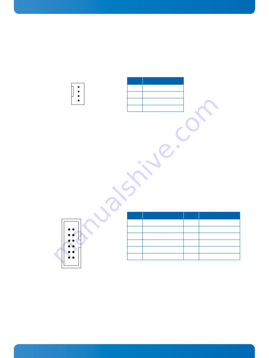
The COMe Ref. Carrier-i T10 TNI provides a 4-pin PWM fan connector, J2, directly controlled by the mod-
ule fan output.
The following figure and table provide pinout information for the PWM fan connector J2.
2.3.12 Front Panel Interface
The COMe Ref. Carrier-i T10 TNI provides a front panel connector, J5, with access to the following signals:
»
HDD activity LED
»
Power LED
»
Power button
»
Reset button
»
Speaker -out (Beep)
The following figure and table provide pinout information for the front panel connector J5.
Figure 11: PWM Fan Connector J2
J2
1
2
3
4
Table 13: PWM Fan Connector J2
PIN
SIGNAL
1
GND
2
12V
3
SENSE
4
PWM Control
Figure 12: Front Panel Connector J5
J5
1
11
2
12
Table 14: Front Panel Connector J5 Pinout
PIN
SIGNAL
PIN
SIGNAL
12
BEEP#
11
GND
10
GND
9
SYS_RESET#
8
GND
7
GND
6
BEEP+
5
PWRBTN#
4
GND
3
ATA_ACT#
2
Po
1


